SLVS023L January   1989  – February 2018 LM285-2.5 , LM385-2.5 , LM385B-2.5

PRODUCTION DATA.  

  1. Features
  2. Applications
  3. Description
    1.     Device Images
      1.      Simplified Schematic
  4. Revision History
  5. Pin Configuration and Functions
    1.     Pin Functions
  6. Specifications
    1. 6.1 Absolute Maximum Ratings
    2. 6.2 ESD Ratings
    3. 6.3 Recommended Operating Conditions
    4. 6.4 Thermal Information
    5. 6.5 Electrical Characteristics
    6. 6.6 Typical Characteristics
  7. Detailed Description
    1. 7.1 Overview
    2. 7.2 Functional Block Diagram
    3. 7.3 Feature Description
    4. 7.4 Device Functional Modes
  8. Application and Implementation
    1. 8.1 Application Information
    2. 8.2 Typical Application
      1. 8.2.1 Design Requirements
      2. 8.2.2 Detailed Design Procedure
      3. 8.2.3 Application Curve
    3. 8.3 System Examples
      1. 8.3.1 Thermocouple Cold-Junction Compensator
      2. 8.3.2 Generating Reference Voltage With a Constant Current Source
  9. Power Supply Recommendations
  10. 10Layout
    1. 10.1 Layout Guidelines
    2. 10.2 Layout Example
  11. 11Device and Documentation Support
    1. 11.1 Related Links
    2. 11.2 Receiving Notification of Documentation Updates
    3. 11.3 Community Resources
    4. 11.4 Trademarks
    5. 11.5 Electrostatic Discharge Caution
    6. 11.6 Glossary
  12. 12Mechanical, Packaging, and Orderable Information

Package Options

Mechanical Data (Package|Pins)
Thermal pad, mechanical data (Package|Pins)
Orderable Information

Typical Characteristics

Data at high and low temperatures are applicable only within the rated operating free-air temperature ranges of the various devices. For conditions shown as MIN or MAX, use the appropriate value specified under recommended operating conditions.
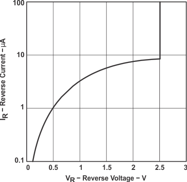
LM285-2.5 LM385-2.5 LM385B-2.5 graph_01_slvs023.gif
TA = 25°C
Figure 1. Reverse Current vs Reverse Voltage
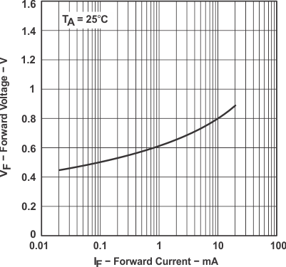
LM285-2.5 LM385-2.5 LM385B-2.5 graph_03_slvs023.gifFigure 3. Forward Voltage vs Forward Current
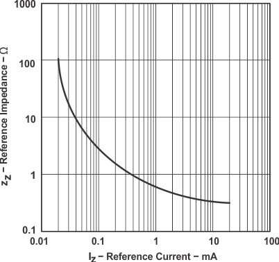
LM285-2.5 LM385-2.5 LM385B-2.5 graph_05_slvs023.gif
f = 25 Hz TA = 25°C
Figure 5. Reference Impedance vs Reference Current
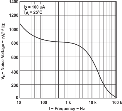
LM285-2.5 LM385-2.5 LM385B-2.5 graph_07_slvs023.gifFigure 7. Noise Voltage vs Frequency
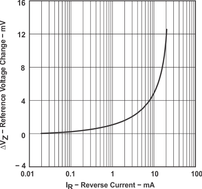
LM285-2.5 LM385-2.5 LM385B-2.5 graph_02_slvs023.gif
TA = 25°C
Figure 2. Reference Voltage Change vs Reverse Current
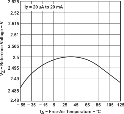
LM285-2.5 LM385-2.5 LM385B-2.5 graph_04_slvs023.gifFigure 4. Reference Voltage vs Free-Air Temperature
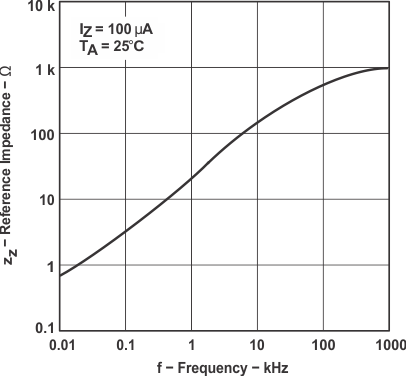
LM285-2.5 LM385-2.5 LM385B-2.5 graph_06_slvs023.gif
Figure 6. Reference Impedance vs Frequency