SCLS303E January 1996 – September 2022 SN54HC640 , SN74HC640
PRODUCTION DATA
- 1 Features
- 2 Description
- 3 Revision History
- 4 Pin Configuration and Functions
- 5 Specifications
- 6 Parameter Measurement Information
- 7 Detailed Description
- 8 Power Supply Recommendations
- 9 Layout
- 10Device and Documentation Support
- 11Mechanical, Packaging, and Orderable Information
Package Options
Refer to the PDF data sheet for device specific package drawings
Mechanical Data (Package|Pins)
- NS|20
- N|20
- DW|20
- PW|20
Thermal pad, mechanical data (Package|Pins)
- PW|20
Orderable Information
6 Parameter Measurement Information
tpd is the maximum between tPLH and tPHL
tt is the maximum between tTLH and tTHL
tdisis the maximum between tPLZ and tPHZ
ten is the maximum between tPZL and tPZH
 Figure 6-1 Load Circuit
 Figure 6-3 Voltage Waveforms
Propagation Delay and Output Transition Times
 Figure 6-5 Voltage Wavefroms
Propagation Delay and Output Transition Times
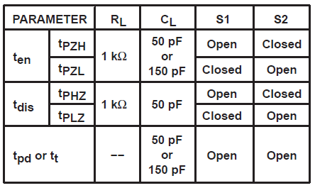 Figure 6-2
  Figure 6-4 Voltage Waveforms
Enable and Disable Times for 3-State Outputs
A. CL includes probe and test-fixture capacitance.
B. Waveform 1 is for an output with
internal conditions such that the output is low except when disabled by the output
control.
Waveform 2 is for an output with internal
conditions such that the output is high except when disabled by the output
control.
C. Phase relationships between waveforms were chosen arbitrarily. All input pulses are supplied by generators having the following characteristics: PRR ≤ 1 MHz, ZO = 50 Ω, tr = 6 ns, tf = 6 ns.
D. The outputs are measured one at a time with one input transition per measurement.