SBOS686A June 2013 – December 2014 TMP451
PRODUCTION DATA.
- 1 Features
- 2 Applications
- 3 Description
- 4 Revision History
- 5 Pin Configuration and Functions
- 6 Specifications
-
7 Detailed Description
- 7.1 Overview
- 7.2 Functional Block Diagram
- 7.3 Feature Description
- 7.4 Device Functional Modes
- 7.5 Programming
- 7.6
Register Map
- 7.6.1
Register Information
- 7.6.1.1 Pointer Register
- 7.6.1.2 Temperature Registers
- 7.6.1.3 Local Temperature High Byte Register (offset: Read = 00h; Write = N/A) [reset = 00h]
- 7.6.1.4 Remote Temperature High Byte Register (offset: Read = 01h; Write = N/A) [reset = 00h]
- 7.6.1.5 Status Register (offset: Read = 02h; Write = N/A) [reset = N/A]
- 7.6.1.6 Configuration Register (offset: Read = 03h; Write = 09h) [reset = 00h]
- 7.6.1.7 Conversion Rate Register (offset: Read = 04h; Write = 0Ah) [reset = 08h]
- 7.6.1.8 Local Temperature High Limit Register (offset: Read = 05h; Write = 0Bh) [reset = 55h]
- 7.6.1.9 Local Temperature Low Limit Register (offset: Read = 06h; Write = 0Ch) [reset = 00h]
- 7.6.1.10 Remote Temperature High Limit High Byte Register (offset: Read = 07h; Write = 0Dh) [reset = 55h]
- 7.6.1.11 Remote Temperature Low Limit High Byte Register (offset: Read = 08h; Write = 0Eh) [reset = 00h]
- 7.6.1.12 One-shot Start Register (offset: Read = N/A; Write = 0Fh) [reset = N/A]
- 7.6.1.13 Remote Temperature Low Byte Register (offset: Read = 10h; Write = N/A) [reset = 00h]
- 7.6.1.14 Remote Temperature Offset High Byte Register (offset: Read = 11h; Write = 11h) [reset = 00h]
- 7.6.1.15 Remote Temperature Offset Low Byte Register (offset: Read = 12h; Write = 12h) [reset = 00h]
- 7.6.1.16 Remote Temperature High Limit Low Byte Register (offset: Read = 13h; Write = 13h) [reset = 00h]
- 7.6.1.17 Remote Temperature Low Limit Low Byte Register (offset: Read = 14h; Write = 14h) [reset = 00h]
- 7.6.1.18 Local Temperature Low Byte Register (offset: Read = 15h; Write = N/A) [reset = 00h]
- 7.6.1.19 Remote Temperature THERM Limit Register (offset: Read = 19h; Write = 19h) [reset = 6C]
- 7.6.1.20 Local Temperature THERM Limit Register (offset: Read = 20h; Write = 20h) [reset = 55]
- 7.6.1.21 THERM Hysteresis Register (offset: Read = 21h; Write = 21h) [reset = 0Ah]
- 7.6.1.22 Consecutive ALERT Register (offset: Read = 22h; Write = 22h) [reset = 01h]
- 7.6.1.23 η-Factor Correction Register (offset: Read = 23h; Write = 23h) [reset = 00h]
- 7.6.1.24 Digital Filter Control Register (offset: Read = 24h; Write = 24h) [reset = 00h]
- 7.6.1.25 Manufacturer ID Register (offset: Read = FEh; Write = N/A) [reset = 55]
- 7.6.1
Register Information
- 8 Application and Implementation
- 9 Power Supply Recommendations
- 10Layout
- 11Device and Documentation Support
- 12Mechanical, Packaging, and Orderable Information
Package Options
Mechanical Data (Package|Pins)
- DQF|8
Thermal pad, mechanical data (Package|Pins)
Orderable Information
8 Application and Implementation
NOTE
Information in the following applications sections is not part of the TI component specification, and TI does not warrant its accuracy or completeness. TI’s customers are responsible for determining suitability of components for their purposes. Customers should validate and test their design implementation to confirm system functionality.
8.1 Application Information
The TMP451 device requires only a transistor connected between the D+ and D– pins for remote temperature measurement. Tie the D+ pin to GND if the remote channel is not used and only the local temperature is measured. The SDA, ALERT, and THERM pins (and SCL, if driven by an open-drain output) require pullup resistors as part of the communication bus. A 0.1-µF power-supply decoupling capacitor is recommended for local bypassing.
8.2 Typical Application
Figure 41 shows the typical configuration for the TMP451 device.
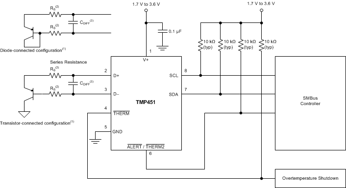
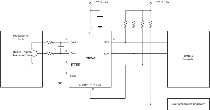 Figure 42. TMP451 Basic Connections Using a Processor Built-In Remote Transistor
8.2.1 Design Requirements
The TMP451 device is designed to be used with either discrete transistors or substrate transistors built into processor chips and ASICs. Either NPN or PNP transistors can be used, as long as the base-emitter junction is used as the remote temperature sense. NPN transistors must be diode-connected. PNP transistors can either be transistor- or diode-connected (see Figure 41).
Errors in remote temperature sensor readings are typically the consequence of the ideality factor and current excitation used by the TMP451 device versus the manufacturer-specified operating current for a given transistor. Some manufacturers specify a high-level and low-level current for the temperature-sensing substrate transistors. The TMP451 device uses 7.5 μA for ILOW and 120 μA for IHIGH.
The ideality factor (η) is a measured characteristic of a remote temperature sensor diode as compared to an ideal diode. The TMP451 allows for different η-factor values; see the η-Factor Correction Register section.
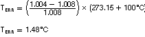
The ideality factor for the TMP451 device is trimmed to be 1.008. For transistors that have an ideality factor that does not match the TMP451, Equation 4 can be used to calculate the temperature error.
NOTE
For the equation to be used correctly, actual temperature (°C) must be converted to Kelvin (K).
where
- TERR = error in the TMP451 device because η ≠ 1.008
- η = ideality factor of remote temperature sensor
- T(°C) = actual temperature
- Degree delta is the same for °C and K.
For η = 1.004 and T(°C) = 100°C:
If a discrete transistor is used as the remote temperature sensor with the TMP451, the best accuracy can be achieved by selecting the transistor according to the following criteria:
- Base-emitter voltage > 0.25 V at 7.5 μA, at the highest sensed temperature.
- Base-emitter voltage < 0.95 V at 120 μA, at the lowest sensed temperature.
- Base resistance < 100 Ω.
- Tight control of VBE characteristics indicated by small variations in hFE (that is, 50 to 150).
Based on this criteria, two recommended small-signal transistors are the 2N3904 (NPN) or 2N3906 (PNP).
8.2.2 Detailed Design Procedure
The local temperature sensor inside the TMP451 device monitors the ambient air around the device. The thermal time constant for the TMP451 device is approximately two seconds. This constant implies that if the ambient air changes quickly by 100°C, it would take the TMP451 device about 10 seconds (that is, five thermal time constants) to settle to within 1°C of the final value. In most applications, the TMP451 package is in electrical, and therefore thermal, contact with the printed circuit board (PCB), as well as subjected to forced airflow. The accuracy of the measured temperature directly depends on how accurately the PCB and forced airflow temperatures represent the temperature that the TMP451 is measuring. Additionally, the internal power dissipation of the TMP451 can cause the temperature to rise above the ambient or PCB temperature. The internal power dissipated as a result of exciting the remote temperature sensor is negligible because of the small currents used. For a 3.3-V supply and maximum conversion rate of 16 conversions per second, the TMP451 device dissipates 0.54 mW (PDIQ = 3.3 V × 165 μA). A θJA of 171.3°C/W causes the junction temperature to rise approximately 0.09°C above the ambient.
The temperature measurement accuracy of the TMP451 device depends on the remote and/or local temperature sensor being at the same temperature as the system point being monitored. Clearly, if the temperature sensor is not in good thermal contact with the part of the system being monitored, then there will be a delay in the response of the sensor to a temperature change in the system. For remote temperature-sensing applications using a substrate transistor (or a small, SOT23 transistor) placed close to the device being monitored, this delay is usually not a concern.
8.2.3 Application Curves
The following curves show the performance capabilities of the TMP451 device. Figure 43 shows the accuracy performance in an oil-bath temperature drift of a population of 16 standrard 2N3906 transistors measured in a diode-connected configuration. Figure 44 shows the typical step response to a submerging of a sensor in an oil bath with temperature of 100°C.
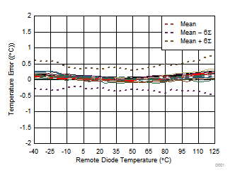 Figure 43. TMP451 Remote Diode Temperature Drift (Diode-Connected 2N3906)
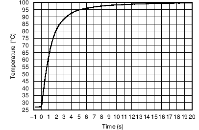 Figure 44. Temperature Step Response