JAJSH19I October   2013  – March 2022 BQ76920 , BQ76930 , BQ76940

PRODMIX  

  1. 特長
  2. アプリケーション
  3. 概要
  4. Revision History
  5. Device Comparison Table
  6. Pin Configuration and Functions
    1. 6.1 Versions
    2. 6.2 BQ76920 Pin Diagram
    3. 6.3 BQ76930 Pin Diagram
    4. 6.4 BQ76940 Pin Diagram
  7. Specifications
    1. 7.1 Absolute Maximum Ratings
    2. 7.2 ESD Ratings
    3. 7.3 Recommended Operating Conditions
    4. 7.4 Thermal Information
    5. 7.5 Electrical Characteristics
    6. 7.6 Timing Requirements
    7. 7.7 Typical Characteristics
  8. Detailed Description
    1. 8.1 Overview
    2. 8.2 Functional Block Diagram
    3. 8.3 Feature Description
      1. 8.3.1 Subsystems
        1. 8.3.1.1 Measurement Subsystem Overview
          1. 8.3.1.1.1 Data Transfer to the Host Controller
          2. 8.3.1.1.2 14-Bit ADC
            1. 8.3.1.1.2.1 Optional Real-Time Calibration Using the Host Microcontroller
          3. 8.3.1.1.3 16-Bit CC
          4. 8.3.1.1.4 External Thermistor
          5. 8.3.1.1.5 Die Temperature Monitor
          6. 8.3.1.1.6 16-Bit Pack Voltage
          7. 8.3.1.1.7 System Scheduler
        2. 8.3.1.2 Protection Subsystem
          1. 8.3.1.2.1 Integrated Hardware Protections
          2. 8.3.1.2.2 Reduced Test Time
        3. 8.3.1.3 Control Subsystem
          1. 8.3.1.3.1 FET Driving (CHG AND DSG)
            1. 8.3.1.3.1.1 High-Side FET Driving
          2. 8.3.1.3.2 Load Detection
          3. 8.3.1.3.3 Cell Balancing
          4. 8.3.1.3.4 Alert
          5. 8.3.1.3.5 Output LDO
        4. 8.3.1.4 Communications Subsystem
    4. 8.4 Device Functional Modes
      1. 8.4.1 NORMAL Mode
      2. 8.4.2 SHIP Mode
    5. 8.5 Register Maps
      1. 8.5.1 Register Details
      2. 8.5.2 Read-Only Registers
  9. Application and Implementation
    1. 9.1 Application Information
      1. 9.1.1 Device Timing
      2. 9.1.2 Random Cell Connection
      3. 9.1.3 Power Pin Diodes
      4. 9.1.4 Alert Pin
      5. 9.1.5 Sense Inputs
      6. 9.1.6 TSn Pins
      7. 9.1.7 Unused Pins
      8. 9.1.8 Configuring Alternative Cell Counts
    2. 9.2 Typical Applications
      1. 9.2.1 Design Requirements
      2. 9.2.2 Detailed Design Procedure
        1. 9.2.2.1 Step-by-Step Design Procedure
      3. 9.2.3 Application Curves
  10. 10Power Supply Recommendations
  11. 11Layout
    1. 11.1 Layout Guidelines
    2. 11.2 Layout Example
  12. 12Device and Documentation Support
    1. 12.1 Third-Party Products Disclaimer
    2. 12.2 Documentation Support
    3. 12.3 Related Links
    4. 12.4 Receiving Notification of Documentation Updates
    5. 12.5 Trademarks
  13. 13Mechanical, Packaging, and Orderable Information

パッケージ・オプション

メカニカル・データ(パッケージ|ピン)
サーマルパッド・メカニカル・データ
発注情報

概要

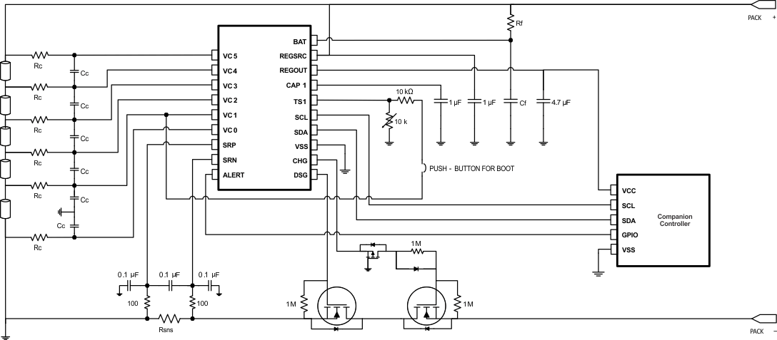
BQ769x0 高信頼性アナログ・フロント・エンド (AFE) デバイス・ファミリは、軽量電気車両、電動工具、無停電電源装置など、次世代大電力システムの包括的なパック監視および保護ソリューションの一部としての役割を果たします。BQ769x0 は、低消費電力を考慮して設計されています。IC 内のサブブロックは、チップ全体の消費電流を制御するために有効または無効にできます。また、シップ・モードを使うと、パックを簡単に超低消費電力状態に移行させることができます。

BQ76920 デバイスは最大 5 直列セルまたは 18V (標準値) パック、BQ76930 は最大 10 直列セルまたは 36V (標準値) パック、BQ76940 は最大 15 直列セルまたは 48V (標準値) パックをそれぞれサポートしています。これらの AFE を使用して、リチウムイオン、リン酸鉄リチウムを含む各種バッテリ・ケミストリを管理できます。ホスト・コントローラで BQ769x0 を I2C 制御することで、多くのバッテリ・パック管理機能 (例:監視 (セル電圧、パック電流、パック温度)、保護 (充放電 FET の制御)、平衡化) を実現できます。内蔵 A/D コンバータを使うと、重要なシステム・パラメータを純粋にデジタル的に読み出すことができます。この A/D コンバータは TI の製造プロセスでキャリブレーション済みです。

製品情報
部品番号 1 パッケージ 本体サイズ (公称)
BQ76920 TSSOP (20) 6.50mm × 4.40mm
BQ76930 TSSOP (30) 7.80mm × 4.40mm
BQ76940 TSSOP (44) 11.00mm × 4.40mm
GUID-D43C0A72-3794-4621-A0EC-1876DBC0DE55-low.gif 概略回路図