JAJSD34C April 2017 – April 2018 CSD88599Q5DC
PRODUCTION DATA.
- 1特長
- 2アプリケーション
- 3概要
- 4改訂履歴
- 5Specifications
-
6Application and Implementation
- 6.1 Application Information
- 6.2 Brushless DC Motor With Trapezoidal Control
- 6.3 Power Loss Curves
- 6.4 Safe Operating Area (SOA) Curve
- 6.5 Normalized Power Loss Curves
- 6.6 Design Example – Regulate Current to Maintain Safe Operation
- 6.7 Design Example – Regulate Board and Case Temperature to Maintain Safe Operation
- 7Layout
- 8デバイスおよびドキュメントのサポート
- 9メカニカル、パッケージ、および注文情報
パッケージ・オプション
デバイスごとのパッケージ図は、PDF版データシートをご参照ください。
メカニカル・データ(パッケージ|ピン)
- DMM|22
サーマルパッド・メカニカル・データ
発注情報
6.2 Brushless DC Motor With Trapezoidal Control
The trapezoidal commutation control is simple and has fewer switching losses compared to sinusoidal control.
 Figure 17. Functional Block Diagram
The block diagram shown in Figure 17 offers a simple instruction of what is required to drive a BLDC motor: one microcontroller, one three-phase driver IC, three power blocks (historically six power MOSFETs) and three Hall effect sensors. The microcontroller responsible for block commutation must always know the rotor orientation or its position relative to the stator coils. This is easy achieved with a brushed DC motor due to the fixed geometry and position of the rotor windings, shaft and commutator.
A three-phase BLDC motor requires three Hall effect sensors or a rotary encoder to detect the rotor position in relation to stator armature windings. With input from these three Hall effect sensors output signals, the microcontroller can determine the proper commutation sequence. The three Hall sensors named A, B, and C are mounted on the stator core at 120° intervals and the stator phase windings are implemented in a star configuration. For every 60° of motor rotation, one Hall sensor changes its state. Based on the Hall sensors' output code, at the end of each block commutation interval the ampere conductors are commutated to the next position. There are 6 steps required to complete a full electrical cycle. The number of block commutation cycles to complete a full mechanical rotation is determined by the number of rotor pole pairs.
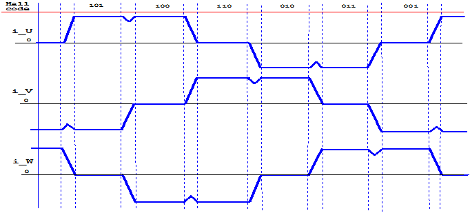
 Figure 18. Winding Current Waveforms on a BLDC Motor
Figure 18 above shows the three phase motor winding currents i_U, i_V, and i_W when running at 100% duty cycle.
Trapezoidal commutation control offers the following advantages:
- Only two windings in series carry the phase winding current at any time while the third winding is open.
- Only one current sensor is necessary for all three windings U, V, and W.
- The position of the current sensor allows the use of low-cost shunt resistors.
However, trapezoidal commutation control has the disadvantage of commutation torque ripple. The current sense on a three-phase inverter can be configured to use a single-shunt or three different sense resistors. For cost sensitive applications targeting sensorless control, the three Hall effect sensors can be replaced with BEMF voltage feedback dividers.
To obtain faster motor rotations and higher revolutions per minute (RPM), shorter periods and higher VIN voltage are necessary. Contrarily, to reduce the rotational speed of the motor, it is necessary to lower the RMS voltage applied across stator windings. This can easily be easily achieved by modulating the duty cycle, while maintain a constant switching frequency. Frequency for the three-phase inverter chosen is usually low between 10 kHz to 50 kHz to reduce winding losses and to avoid audible noise.