JAJSM35B December   2015  – July 2021 LM53625-Q1 , LM53635-Q1

PRODUCTION DATA  

  1. 特長
  2. アプリケーション
  3. 概要
  4. Revision History
  5. Device Comparison
  6. Pin Configuration and Functions
  7. Specifications
    1. 7.1 Absolute Maximum Ratings
    2. 7.2 ESD Ratings
    3. 7.3 Recommended Operating Conditions
    4. 7.4 Thermal Information
    5. 7.5 Electrical Characteristics
    6. 7.6 System Characteristics
    7. 7.7 Timing Characteristics
    8. 7.8 Typical Characteristics
  8. Detailed Description
    1. 8.1 Overview
    2. 8.2 Functional Block Diagram
      1. 8.2.1 Control Scheme
    3. 8.3 Feature Description
      1. 8.3.1 RESET Flag Output
      2. 8.3.2 Enable and Start-Up
      3. 8.3.3 Soft-Start Function
      4. 8.3.4 Current Limit
      5. 8.3.5 Hiccup Mode
      6. 8.3.6 Synchronizing Input
      7. 8.3.7 Undervoltage Lockout (UVLO) and Thermal Shutdown (TSD)
      8. 8.3.8 Input Supply Current
    4. 8.4 Device Functional Modes
      1. 8.4.1 AUTO Mode
      2. 8.4.2 FPWM Mode
      3. 8.4.3 Dropout
      4. 8.4.4 Input Voltage Frequency Foldback
    5. 8.5 Spread-Spectrum Operation
  9. Application and Implementation
    1. 9.1 Application Information
    2. 9.2 Typical Applications
      1. 9.2.1 General Application
        1. 9.2.1.1 Design Requirements
        2. 9.2.1.2 Detailed Design Procedure
          1. 9.2.1.2.1 External Components Selection
            1. 9.2.1.2.1.1 Input Capacitors
              1. 9.2.1.2.1.1.1 Input Capacitor Selection
            2. 9.2.1.2.1.2 Output Inductors and Capacitors Selection
              1. 9.2.1.2.1.2.1 Inductor Selection
              2. 9.2.1.2.1.2.2 Output Capacitor Selection
          2. 9.2.1.2.2 Setting the Output Voltage
            1. 9.2.1.2.2.1 FB for Adjustable Versions
          3. 9.2.1.2.3 VCC
          4. 9.2.1.2.4 BIAS
          5. 9.2.1.2.5 CBOOT
          6. 9.2.1.2.6 Maximum Ambient Temperature
        3. 9.2.1.3 Application Curves
      2. 9.2.2 Fixed 5-V Output for USB-Type Applications
        1. 9.2.2.1 Design Requirements
        2. 9.2.2.2 Detailed Design Procedure
        3. 9.2.2.3 Application Curves
      3. 9.2.3 Fixed 3.3-V Output
        1. 9.2.3.1 Design Requirements
        2. 9.2.3.2 Detailed Design Procedure
        3. 9.2.3.3 Application Curves
      4. 9.2.4 Adjustable Output
        1. 9.2.4.1 Design Requirements
        2. 9.2.4.2 Detailed Design Procedure
        3. 9.2.4.3 Application Curves
    3. 9.3 What to Do and What Not to Do
  10. 10Power Supply Recommendations
  11. 11Layout
    1. 11.1 Layout Guidelines
    2. 11.2 Layout Example
  12. 12Device and Documentation Support
    1. 12.1 Device Support
      1. 12.1.1 Third-Party Products Disclaimer
    2. 12.2 Documentation Support
      1. 12.2.1 Related Documentation
    3. 12.3 Receiving Notification of Documentation Updates
    4. 12.4 サポート・リソース
    5. 12.5 Trademarks
    6. 12.6 Electrostatic Discharge Caution
    7. 12.7 Glossary
  13. 13Mechanical, Packaging, and Orderable Information

パッケージ・オプション

デバイスごとのパッケージ図は、PDF版データシートをご参照ください。

メカニカル・データ(パッケージ|ピン)
  • RNL|22
サーマルパッド・メカニカル・データ
発注情報

概要

LM53625-Q1/LM53635-Q1 同期整流式降圧レギュレータは車載用アプリケーションに最適化されており、5V、3.3V、可変出力のいずれかを出力します。高度な高速回路により、LM53625-Q1/LM53635-Q1 は 2.1MHz の固定周波数で 18V の入力から 3.3V の出力をレギュレートできます。革新的なアーキテクチャにより、このデバイスはわずか 3.55V の入力電圧から 3.3V の出力をレギュレートできます。LM53625-Q1/LM53635-Q1 のあらゆる要素は、車載用顧客と性能を重視する産業用顧客のために最適化されています。最高 36V の入力電圧と、最高 42V の過渡耐圧により、入力サージ保護の設計が簡単になります。車載認定済みのウェッタブル・フランク付き HotRod QFN パッケージは、寄生インダクタンスおよび抵抗を低減すると同時に、効率の向上、スイッチ・ノード・リンギングの最小化、電磁干渉 (EMI) の大幅な低減を実現します。フィルタリングと遅延を備えたオープン・ドレインのリセット出力により、システムの真の状態を示すことができます。この機能により、追加のスーパーバイザ部品が必要なくなるため、コストと基板面積を削減できます。PWM モードと PFM モードの間のシームレスな遷移と、小さい静止電流 (3.3V オプションでわずか 15µA) により、あらゆる負荷で高い効率と優れた過渡応答を実現します。

製品情報
型番 パッケージ(1) 本体サイズ
LM53625-Q1 VQFN-HR (22) 5.00mm × 4.00mm
LM53635-Q1
利用可能なすべてのパッケージについては、このデータシートの末尾にある注文情報を参照してください。
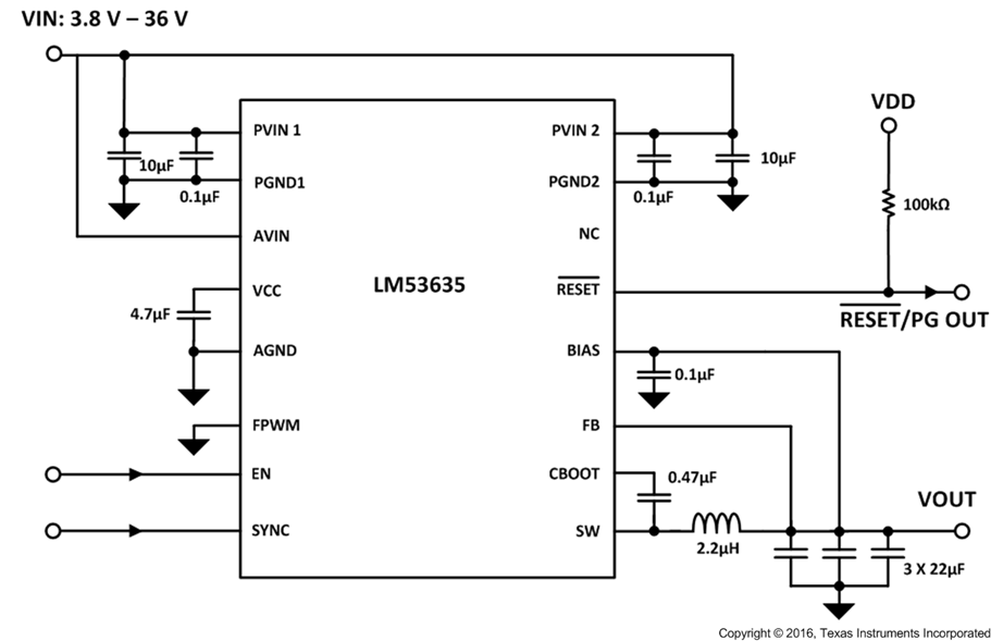
GUID-F7D28089-A1A8-4F22-9203-409FBAD41580-low.png代表的なアプリケーション回路
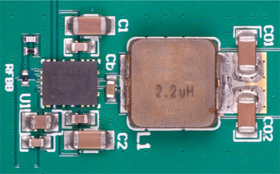
GUID-0C7B6AB8-B819-437B-876D-7EAF4AB75CE0-low.jpg代表的な車載用のレイアウト (22mm x 12.5mm)