JAJS972M November 2001 – September 2016 LMV981-N , LMV982-N
PRODUCTION DATA.
- 1 特長
- 2 アプリケーション
- 3 概要
- 4 改訂履歴
- 5 Description (continued)
- 6 Pin Configuration and Functions
-
7 Specifications
- 7.1 Absolute Maximum Ratings
- 7.2 ESD Ratings
- 7.3 Recommended Operating Conditions
- 7.4 Thermal Information
- 7.5 Electrical Characteristics - DC, 1.8 V
- 7.6 Electrical Characteristics - AC, 1.8 V
- 7.7 Electrical Characteristics - DC, 2.7 V
- 7.8 Electrical Characteristics - AC, 2.7 V
- 7.9 Electrical Characteristics - DC, 5 V
- 7.10 Electrical Characteristics - AC, 5 V
- 7.11 Typical Characteristics
- 8 Detailed Description
- 9 Application and Implementation
- 10Power Supply Recommendations
- 11Layout
- 12デバイスおよびドキュメントのサポート
- 13メカニカル、パッケージ、および注文情報
パッケージ・オプション
メカニカル・データ(パッケージ|ピン)
サーマルパッド・メカニカル・データ
- DCK|6
発注情報
11 Layout
11.1 Layout Guidelines
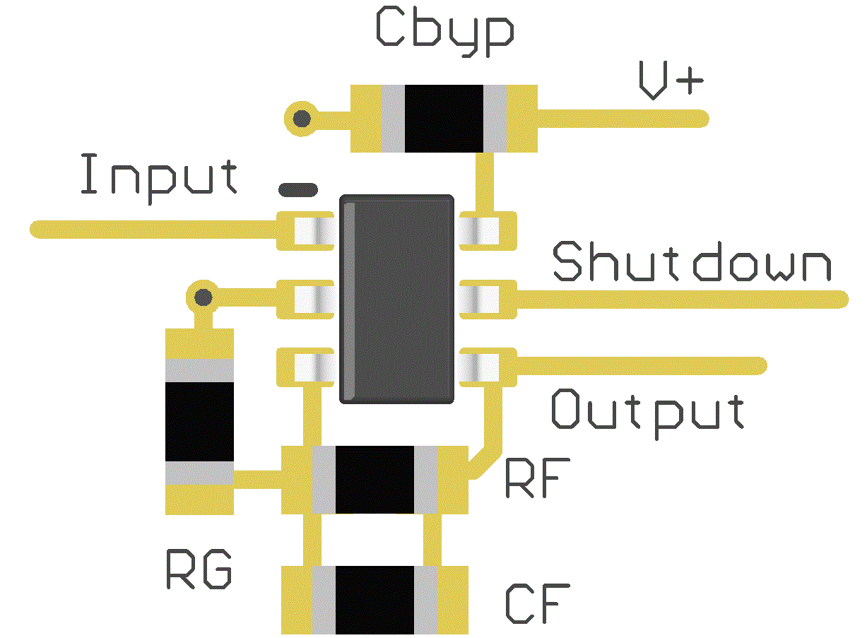
The V+ pin must be bypassed to ground with a low-ESR capacitor.
The optimum placement is closest to the V+ and ground pins.
Take care to minimize the loop area formed by the bypass capacitor connection between V+ and ground.
The ground pin must be connected to the PCB ground plane at the pin of the device.
The feedback components must be placed as close to the device as possible minimizing strays.
11.2 Layout Example
 Figure 38. SOT-23 Layout Example