JAJSC83E May 2016 – January 2021 TPS25940-Q1
PRODMIX
- 1 特長
- 2 アプリケーション
- 3 概要
- 4 Revision History
- 5 Device Comparison Table
- 6 Pin Configuration and Functions
- 7 Specifications
- 8 Parametric Measurement Information
-
9 Detailed Description
- 9.1 Overview
- 9.2 Functional Block Diagram
- 9.3 Feature Description
- 9.4 Device Functional Modes
-
10Application and Implementation
- 10.1 Application Information
- 10.2
Typical Application
- 10.2.1 Design Requirements
- 10.2.2
Detailed Design Procedure
- 10.2.2.1 Step by Step Design Procedure
- 10.2.2.2 Programming the Current-Limit Threshold: R(ILIM) Selection
- 10.2.2.3 Undervoltage Lockout and Overvoltage Set Point
- 10.2.2.4 Programming Current Monitoring Resistor—RIMON
- 10.2.2.5 Setting Output Voltage Ramp Time (tdVdT)
- 10.2.2.6 Programing the Power Good Set Point
- 10.2.2.7 Support Component Selections—R6, R7 and CIN
- 10.2.3 Application Curves
- 10.2.4 System Examples
- 11Power Supply Recommendations
- 12Layout
- 13Device and Documentation Support
- 14Mechanical, Packaging, and Orderable Information
パッケージ・オプション
メカニカル・データ(パッケージ|ピン)
- RVC|20
サーマルパッド・メカニカル・データ
- RVC|20
発注情報
3 概要
TPS25940xx-Q1 eFuse電力スイッチは、小型で豊富な機能を持つ電力管理デバイスで、完全な保護機能のセットが内蔵されています。動作電圧範囲が広いため、多くの一般的な DC バス電圧の制御が可能です。バック・ツー・バックのFETが内蔵され、双方向の電流制御を行います。それにより、障害が発生した電源バスに対して負荷側のホールドアップ・エネルギーの逆流が許容されないようなシステムに最適です。
負荷、ソース、およびデバイス保護が提供され、過電流、dVo/dt ランプ、過電圧と低電圧のスレッショルドなど、多くの機能がプログラム可能です。システム・ステータスの監視や下流負荷の制御のため、PGOOD、FLT、および高精度の電流監視出力を備えています。高精度でプログラム可能な低電圧および過電圧のスレッショルドとモードにより、電力管理の設計が容易になります。
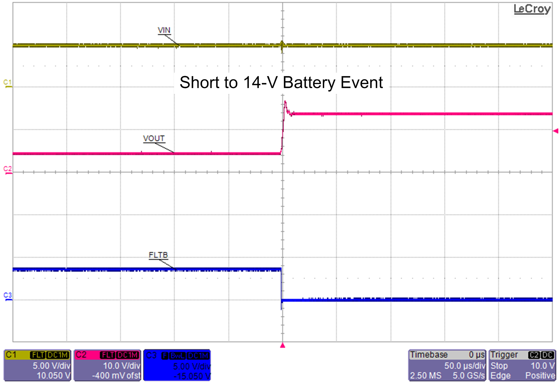
TPS25940xx-Q1は、V(IN) および V(OUT) を監視し、V(IN) < (V(OUT) – 66mV) のときに真の逆電流保護を提供します。この機能によって、出力とバッテリとの短絡障害が発生したとき、電源バスが過電圧から保護されます。
製品情報(1)
| 部品番号 | パッケージ | 本体サイズ (公称) |
|---|---|---|
| TPS25940-Q1 | WQFN (20) | 3.00mm×4.00mm |
| TPS25940L-Q1 | ||
| TPS259401A-Q1 |
(1) 利用可能なパッケージについては、このデータシートの末尾にある注文情報を参照してください。
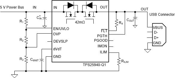
 概略回路図
概略回路図 出力とバッテリ間の短絡検出と保護