JAJSC03E january   2014  – may 2023 TPS562200 , TPS563200

PRODUCTION DATA  

  1.   1
  2. 特長
  3. アプリケーション
  4. 概要
  5. Revision History
  6. Pin Configuration and Functions
  7. Specifications
    1. 6.1 Absolute Maximum Ratings #GUID-10807E29-2FD4-4A3F-94B2-FDEBD147A133/SLVSC819633
    2. 6.2 ESD Ratings
    3. 6.3 Recommended Operating Conditions
    4. 6.4 Thermal Information
    5. 6.5 Electrical Characteristics
    6. 6.6 Timing Requirements
    7. 6.7 Typical Characteristics TPS562200
    8. 6.8 Typical Characteristics TPS563200
  8. Detailed Description
    1. 7.1 Overview
    2. 7.2 Functional Block Diagram
    3. 7.3 Feature Description
      1. 7.3.1 The Adaptive On-Time Control And PWM Operation
      2. 7.3.2 Advanced Eco-mode Control
      3. 7.3.3 Soft Start And Pre-Biased Soft Start
      4. 7.3.4 Current Protection
      5. 7.3.5 Over Voltage Protection
      6. 7.3.6 UVLO Protection
      7. 7.3.7 Thermal Shutdown
    4. 7.4 Device Functional Modes
      1. 7.4.1 Normal Operation
      2. 7.4.2 Eco-mode Operation
      3. 7.4.3 Standby Operation
  9. Application and Implementation
    1. 8.1 Application Information
    2. 8.2 Typical Applications
      1. 8.2.1 Tps562200 4.5-V To 17-V Input, 1.05-V Output Converter
        1. 8.2.1.1 Design Requirements
        2. 8.2.1.2 Detailed Design Procedures
          1. 8.2.1.2.1 Custom Design with WEBENCH® Tools
          2. 8.2.1.2.2 Output Voltage Resistors Selection
          3. 8.2.1.2.3 Output Filter Selection
          4. 8.2.1.2.4 Input Capacitor Selection
          5. 8.2.1.2.5 Bootstrap Capacitor Selection
        3. 8.2.1.3 Application Curves
      2. 8.2.2 Tps563200 4.5-V To 17-V Input, 1.05-V Output Converter
        1. 8.2.2.1 Design Requirements
        2. 8.2.2.2 Detailed Design Procedures
          1. 8.2.2.2.1 Output Filter Selection
        3. 8.2.2.3 Application Curves
    3. 8.3 Power Supply Recommendations
    4. 8.4 Layout
      1. 8.4.1 Layout Guidelines
      2. 8.4.2 Layout Example
  10. Device and Documentation Support
    1. 9.1 Device Support
      1. 9.1.1 Development Support
        1. 9.1.1.1 Custom Design with WEBENCH® Tools
    2. 9.2 ドキュメントの更新通知を受け取る方法
    3. 9.3 サポート・リソース
    4. 9.4 Trademarks
    5. 9.5 静電気放電に関する注意事項
    6. 9.6 用語集
  11. 10Mechanical, Packaging, And Orderable Information

パッケージ・オプション

メカニカル・データ(パッケージ|ピン)
サーマルパッド・メカニカル・データ
発注情報

概要

TPS562200 および TPS563200 は、シンプルで使いやすい 2A および 3A 同期整流降圧 (バック) コンバータで、6ピン SOT-23 パッケージで供給されます。

このデバイスは最小の外付け部品数で動作し、スタンバイ電流が小さくなるよう最適化されています。

これらのスイッチ・モード電源 (SMPS) デバイスは、D-CAP2 制御トポロジを採用し、高速の過渡応答を実現します。また、特殊ポリマーなど ESR (等価直列抵抗) の低い出力コンデンサと、超低 ESR のセラミック・コンデンサの両方を、外部補償部品なしでサポートします。

TPS562200 および TPS563200 は、高度な Eco-mode を搭載し、軽負荷動作中も高効率を維持します。1.6mm × 2.9mm の 6ピン SOT (DDC) パッケージで供給され、周囲温度 –40℃~85℃で仕様が規定されています。

製品情報 (1)
部品番号出力電流 (最大値)パッケージ
TPS5622002ADRL (SOT-236、6)
TPS563200 3A
利用可能なすべてのパッケージについては、データシートの末尾にある注文情報を参照してください。
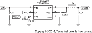
GUID-077A5829-48D9-4562-8A11-148676F40ED6-low.gif簡略回路図
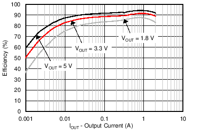
GUID-76550751-A8F8-40AE-8C0B-C816A4AA2019-low.pngTPS562200 の効率