JAJSF59E December   2014  – March 2022 TPS62406-Q1 , TPS62407-Q1 , TPS62422-Q1 , TPS62423-Q1 , TPS62424-Q1

PRODUCTION DATA  

  1. 特長
  2. アプリケーション
  3. 概要
  4. Revision History
  5. Device Comparison Table
  6. Pin Configuration and Functions
  7. Specifications
    1. 7.1 Absolute Maximum Ratings
    2. 7.2 ESD Ratings
    3. 7.3 Recommended Operating Conditions
    4. 7.4 Thermal Information
    5. 7.5 Electrical Characteristics
    6. 7.6 Timing Requirements
    7. 7.7 Switching Characteristics
    8. 7.8 Typical Characteristics
  8. Detailed Description
    1. 8.1 Overview
      1. 8.1.1 Converter 1
      2. 8.1.2 Converter 2
    2. 8.2 Functional Block Diagram
    3. 8.3 Feature Description
      1. 8.3.1 Enable
      2. 8.3.2 DEF_1 Pin Function
      3. 8.3.3 180° Out-of-Phase Operation
      4. 8.3.4 Short-Circuit Protection
      5. 8.3.5 Thermal Shutdown
      6. 8.3.6 EasyScale Interface: One-Pin Serial Interface for Dynamic Output-Voltage Adjustment
        1. 8.3.6.1 General
        2. 8.3.6.2 Protocol
    4. 8.4 Device Functional Modes
      1. 8.4.1 Power-Save Mode
        1. 8.4.1.1 Dynamic Voltage Positioning
        2. 8.4.1.2 Soft Start
        3. 8.4.1.3 100% Duty-Cycle Low-Dropout Operation
        4. 8.4.1.4 Undervoltage Lockout
      2. 8.4.2 Mode Selection
    5. 8.5 Programming
      1. 8.5.1 Addressable Registers
        1. 8.5.1.1 Bit Decoding
        2. 8.5.1.2 Acknowledge
        3. 8.5.1.3 Mode Selection
  9. Application and Implementation
    1. 9.1 Application Information
      1. 9.1.1 Application Information
    2. 9.2 Typical Application
      1. 9.2.1 Design Requirements
      2. 9.2.2 Detailed Design Procedure
        1. 9.2.2.1 Output Voltage Setting
          1. 9.2.2.1.1 Converter 1 Fixed Default Output-Voltage Setting
          2. 9.2.2.1.2 Converter 2 Fixed Default Output-Voltage Setting
        2. 9.2.2.2 Output Filter Design (Inductor and Output Capacitor)
          1. 9.2.2.2.1 Inductor Selection
          2. 9.2.2.2.2 Output-Capacitor Selection
          3. 9.2.2.2.3 Input Capacitor Selection
      3. 9.2.3 Application Curves
    3. 9.3 System Examples
  10. 10Power Supply Recommendations
  11. 11Layout
    1. 11.1 Layout Guidelines
    2. 11.2 Layout Example
  12. 12Device and Documentation Support
    1. 12.1 サポート・リソース
    2. 12.2 Receiving Notification of Documentation Updates
    3. 12.3 Trademarks
    4. 12.4 Electrostatic Discharge Caution
    5. 12.5 Glossary
  13. 13Mechanical, Packaging, and Orderable Information

パッケージ・オプション

メカニカル・データ(パッケージ|ピン)
サーマルパッド・メカニカル・データ
発注情報

概要

TPS624xx-Q1 ファミリのデバイスは、先進運転支援システム (ADAS) など車載アプリケーション用の同期デュアル降圧 DC-DC コンバータです。これらのデバイスは、標準の 3.3V または 5V 電圧レールで給電される 2 つの独立した出力電圧レールと、ADAS カメラ・モジュールの CMOS イメージャまたはシリアライザ - デシリアライザに給電するために最適化された固定電圧を備えています。

EasyScale™ シリアル・インターフェイスにより、動作中に出力電圧の変更が可能です。固定出力電圧バージョンの TPS624xx-Q1 は、低消費電力プロセッサ向けに、1 ピンで制御される単純な動的電圧スケーリングをサポートしています。

TPS624xx-Q1 ファミリのデバイスは 2.25MHz の固定スイッチング周波数で動作し、負荷電流が軽いときはパワー・セーブ・モードに移行し、負荷電流の全範囲について高い効率を維持します。低ノイズのアプリケーションでは、MODE/DATA ピンを HIGH にして、デバイスを強制的に固定周波数の PWM モードにすることもできます。シャットダウン・モードでは、消費電流が 1.2μA (標準値) に低下します。このデバイスは小さなインダクタとコンデンサを使用できるため、ソリューションを小型化できます。

製品情報(1)
部品番号 パッケージ 本体サイズ (公称)
TPS62406-Q1 VSON (10) 3.00mm × 3.00mm
TPS62407-Q1
TPS62422-Q1
TPS62423-Q1
TPS62424-Q1
利用可能なパッケージについては、このデータシートの末尾にある注文情報を参照してください。
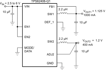
GUID-578B43C7-597E-4287-8358-021A5FE67C1F-low.gif概略回路図
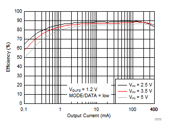
GUID-CA5194FC-135F-470A-AF05-9C6B823A9463-low.gifTPS62406-Q1 の効率と出力電流 VOUT2 との関係