JAJSI06A September   2019  – December 2020 TPSM82810 , TPSM82813

PRODUCTION DATA  

  1. 特長
  2. アプリケーション
  3. 概要
  4. Revision History
  5. Device Comparison Table
  6. Pin Configuration and Functions
  7. Specifications
    1. 7.1 Absolute Maximum Ratings
    2. 7.2 ESD Ratings
    3. 7.3 Recommended Operating Conditions
    4. 7.4 Thermal Information
    5. 7.5 Electrical Characteristics
    6. 7.6 Typical Characteristics
  8. Parameter Measurement Information
    1. 8.1 Schematic
  9. Detailed Description
    1. 9.1 Overview
    2. 9.2 Functional Block Diagram
    3. 9.3 Feature Description
      1. 9.3.1 Precise Enable (EN)
      2. 9.3.2 Output Discharge
      3. 9.3.3 COMP/FSET
      4. 9.3.4 MODE/SYNC
      5. 9.3.5 Spread Spectrum Clocking (SSC) - TPSM8281xS
      6. 9.3.6 Undervoltage Lockout (UVLO)
      7. 9.3.7 Power-Good Output (PG)
      8. 9.3.8 Thermal Shutdown
    4. 9.4 Device Functional Modes
      1. 9.4.1 Pulse Width Modulation (PWM) Operation
      2. 9.4.2 Power Save Mode Operation (PFM/PWM)
      3. 9.4.3 100% Duty-Cycle Operation
      4. 9.4.4 Current Limit and Short Circuit Protection
      5. 9.4.5 Soft Start / Tracking (SS/TR)
  10. 10Application and Implementation
    1. 10.1 Application Information
    2. 10.2 Typical Application
      1. 10.2.1 Design Requirements
      2. 10.2.2 Detailed Design Procedure
        1. 10.2.2.1 Programming the Output Voltage
        2. 10.2.2.2 Feedforward capacitor
        3. 10.2.2.3 Input Capacitor
        4. 10.2.2.4 Output Capacitor
        5. 10.2.2.5 Application Curves
    3. 10.3 System Examples
      1. 10.3.1 Voltage Tracking
      2. 10.3.2 Synchronizing to an External Clock
  11. 11Power Supply Recommendations
  12. 12Layout
    1. 12.1 Layout Guidelines
    2. 12.2 Layout Example
      1. 12.2.1 Thermal Consideration
  13. 13Device and Documentation Support
    1. 13.1 Device Support
      1. 13.1.1 Third-Party Products Disclaimer
    2. 13.2 Documentation Support
      1. 13.2.1 Related Documentation
    3. 13.3 ドキュメントの更新通知を受け取る方法
    4. 13.4 サポート・リソース
    5. 13.5 Trademarks
    6. 13.6 静電気放電に関する注意事項
    7. 13.7 用語集
  14. 14Mechanical, Packaging, and Orderable Information

パッケージ・オプション

メカニカル・データ(パッケージ|ピン)
サーマルパッド・メカニカル・データ
発注情報

Voltage Tracking

The SS/TR pin is externally driven by another voltage source to achieve output voltage tracking. The application circuit is shown in Figure 10-21. From 0 V to 0.6 V, the internal reference voltage to the internal error amplifier follows the SS/TR pin voltage. When the SS/TR pin voltage is above 0.6 V, the voltage tracking is disabled and the FB pin voltage is regulated at 0.6 V. The device achieves ratiometric or coincidental (simultaneous) output tracking, as shown in Figure 10-22.

The R2 value should be set properly to achieve accurate voltage tracking by taking the 2.5-μA charging current into account. 1 kΩ or smaller is a sufficient value for R2. For decreasing SS/TR pin voltage, the device does not sink current from the output when the device is in PFM mode. The resulting decrease of the output voltage can be slower than the SS/TR pin voltage if the load is light. When driving the SS/TR pin with an external voltage, do not exceed the voltage rating of the SS/TR pin which is VIN+0.3 V.
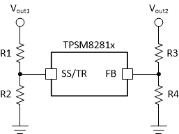
GUID-05436736-9C8B-4FCD-BCE5-AA812C61B907-low.gifFigure 10-21 Schematic for Output Voltage Tracking
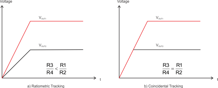
GUID-5B021CEC-16B3-4297-BE9F-3028DF33F5E0-low.pngFigure 10-22 Output Voltage Tracking