JAJSDN0 August 2017 TUSB8041A
PRODUCTION DATA.
- 1 特長
- 2 アプリケーション
- 3 概要
- 4 改訂履歴
- 5 概要(続き)
- 6 Pin Configuration and Functions
- 7 Specifications
-
8 Detailed Description
- 8.1 Overview
- 8.2 Functional Block Diagram
- 8.3 Feature Description
- 8.4 Device Functional Modes
- 8.5
Register Maps
- 8.5.1 Configuration Registers
- 8.5.2 ROM Signature Register
- 8.5.3 Vendor ID LSB Register
- 8.5.4 Vendor ID MSB Register
- 8.5.5 Product ID LSB Register
- 8.5.6 Product ID MSB Register
- 8.5.7 Device Configuration Register
- 8.5.8 Battery Charging Support Register
- 8.5.9 Device Removable Configuration Register
- 8.5.10 Port Used Configuration Register
- 8.5.11 Device Configuration Register 2
- 8.5.12 USB 2.0 Port Polarity Control Register
- 8.5.13 UUID Registers
- 8.5.14 Language ID LSB Register
- 8.5.15 Language ID MSB Register
- 8.5.16 Serial Number String Length Register
- 8.5.17 Manufacturer String Length Register
- 8.5.18 Product String Length Register
- 8.5.19 Device Configuration Register 3
- 8.5.20 USB 2.0 Only Port Register
- 8.5.21 Serial Number String Registers
- 8.5.22 Manufacturer String Registers
- 8.5.23 Product String Registers
- 8.5.24 Additional Feature Configuration Register
- 8.5.25 SMBus Device Status and Command Register
-
9 Applications and Implementation
- 9.1 Application Information
- 9.2
Typical Application
- 9.2.1
Discrete USB Hub Product
- 9.2.1.1 Design Requirements
- 9.2.1.2
Detailed Design Procedure
- 9.2.1.2.1 Upstream Port Implementation
- 9.2.1.2.2 Downstream Port 1 Implementation
- 9.2.1.2.3 Downstream Port 2 Implementation
- 9.2.1.2.4 Downstream Port 3 Implementation
- 9.2.1.2.5 Downstream Port 4 Implementation
- 9.2.1.2.6 VBUS Power Switch Implementation
- 9.2.1.2.7 Clock, Reset, and Misc
- 9.2.1.2.8 TUSB8041A Power Implementation
- 9.2.1.3 Application Curves
- 9.2.1
Discrete USB Hub Product
- 10Power Supply Recommendations
- 11Layout
- 12デバイスおよびドキュメントのサポート
- 13メカニカル、パッケージ、および注文情報
パッケージ・オプション
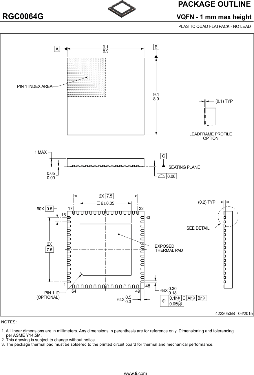
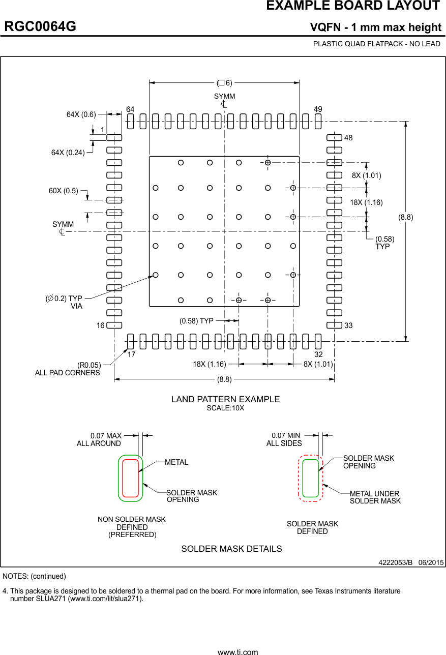
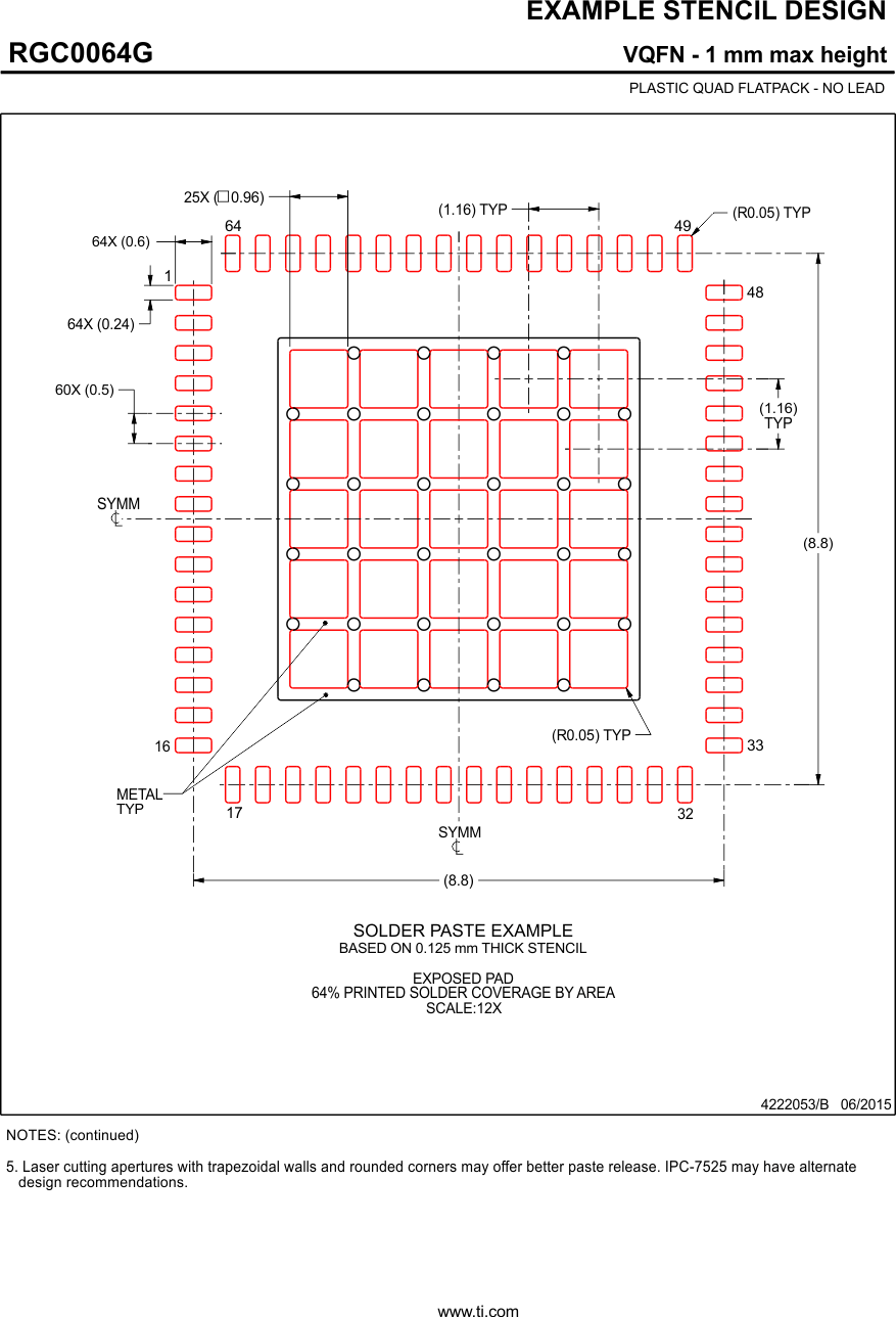
デバイスごとのパッケージ図は、PDF版データシートをご参照ください。
メカニカル・データ(パッケージ|ピン)
- RGC|64
サーマルパッド・メカニカル・データ
発注情報
13 メカニカル、パッケージ、および注文情報
以降のページには、メカニカル、パッケージ、および注文に関する情報が記載されています。これらの情報は、指定のデバイスに対して提供されている最新のデータです。このデータは予告なく変更されることがあり、ドキュメントが改訂される場合もあります。本データシートのブラウザ版を使用されている場合は、画面左側の説明をご覧ください。


