JAJSHM6E june   2019  – february 2021 UCC256402 , UCC256403 , UCC256404

PRODUCTION DATA  

  1.   1
  2. 特長
  3. アプリケーション
  4. 概要
  5. Revision History
  6.   Device Comparison Table
  7. Pin Configuration and Functions
    1.     Pin Functions
  8. Specifications
    1. 6.1 Absolute Maximum Ratings
    2. 6.2 ESD Ratings
    3. 6.3 Recommended Operating Conditions
    4. 6.4 Thermal Information
    5. 6.5 Electrical Characteristics
    6. 6.6 Switching Characteristics
    7. 6.7 Typical Characteristics
  9. Detailed Description
    1. 7.1 Overview
    2. 7.2 Functional Block Diagram
    3. 7.3 Feature Description
      1. 7.3.1 Hybrid Hysteretic Control
      2. 7.3.2 Regulated 13-V Supply
      3. 7.3.3 Feedback Chain
        1. 7.3.3.1 Optocoupler Feedback Signal Input and Bias
        2. 7.3.3.2 FB Pin Voltage Clamp
        3. 7.3.3.3 "Pick Lower Value" Block and Soft Start Multiplexer
        4. 7.3.3.4 Pick Higher Block and Burst Mode Multiplexer
        5. 7.3.3.5 VCR Comparators
      4. 7.3.4 Resonant Capacitor Voltage Sensing
      5. 7.3.5 Resonant Current Sensing
      6. 7.3.6 Bulk Voltage Sensing
      7. 7.3.7 Output Voltage Sensing
      8. 7.3.8 High Voltage Gate Driver
        1. 7.3.8.1 Adaptive Dead Time Control
      9. 7.3.9 Protections
        1. 7.3.9.1 ZCS Region Prevention
        2. 7.3.9.2 Over Current Protection (OCP)
        3. 7.3.9.3 Bias Winding Over Voltage Protection (BWOVP)
        4. 7.3.9.4 Input Under Voltage Protection (VINUVP)
        5. 7.3.9.5 Input Over Voltage Protection (VINOVP)
        6. 7.3.9.6 Boot UVLO
        7. 7.3.9.7 RVCC UVLO
        8. 7.3.9.8 Over Temperature Protection (OTP)
    4. 7.4 Device Functional Modes
      1. 7.4.1 High Voltage Start-Up
      2. 7.4.2 X-Capacitor Discharge
      3. 7.4.3 Burst Mode Control
        1. 7.4.3.1 Soft-Start and Burst-Mode Threshold
        2. 7.4.3.2 BMTL/BMTH Ratio Programming
      4. 7.4.4 System State Machine
  10.   Application and Implementation
    1. 8.1 Application Information
    2. 8.2 Typical Application
      1. 8.2.1 Design Requirements
      2. 8.2.2 Detailed Design Procedure
        1. 8.2.2.1  LLC Power Stage Requirements
        2. 8.2.2.2  LLC Gain Range
        3. 8.2.2.3  Select Ln and Qe
        4. 8.2.2.4  Determine Equivalent Load Resistance
        5. 8.2.2.5  Determine Component Parameters for LLC Resonant Circuit
        6. 8.2.2.6  LLC Primary-Side Currents
        7. 8.2.2.7  LLC Secondary-Side Currents
        8. 8.2.2.8  LLC Transformer
        9. 8.2.2.9  LLC Resonant Inductor
        10. 8.2.2.10 LLC Resonant Capacitor
        11. 8.2.2.11 LLC Primary-Side MOSFETs
        12. 8.2.2.12 LLC Rectifier Diodes
        13. 8.2.2.13 LLC Output Capacitors
        14. 8.2.2.14 HV Pin Series Resistors
        15. 8.2.2.15 BLK Pin Voltage Divider
        16. 8.2.2.16 ISNS Pin Differentiator
        17. 8.2.2.17 VCR Pin Capacitor Divider
        18. 8.2.2.18 BW Pin Voltage Divider
        19. 8.2.2.19 Soft Start and Burst Mode Programming
      3. 8.2.3 Application Curves
  11. Power Supply Recommendations
    1. 8.1 VCC Pin Capacitor
    2. 8.2 Boot Capacitor
    3. 8.3 RVCC Pin Capacitor
  12. Layout
    1. 9.1 Layout Guidelines
    2. 9.2 Layout Example
  13. 10Device and Documentation Support
    1. 10.1 Documentation Support
      1. 10.1.1 Related Documentation
    2. 10.2 Related Links
    3. 10.3 Receiving Notification of Documentation Updates
    4. 10.4 Community Resources
    5. 10.5 Trademarks
  14.   Mechanical, Packaging, and Orderable Information

パッケージ・オプション

メカニカル・データ(パッケージ|ピン)
サーマルパッド・メカニカル・データ
発注情報

概要

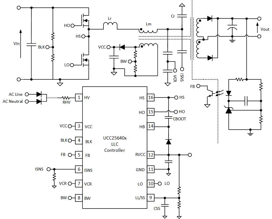
UCC25640x は、高電圧ゲート・ドライバを内蔵したフル機能の LLC コントローラです。本デバイスは、最小限の外付け部品で完全な電源システムを構築するため、PFC コントローラと組み合わせるように設計されています。その結果完成する電源システムは、スタンバイ電力コンバータを別途必要とせずに、スタンバイ電力の最も厳格な要件を満たすように設計されています。

UCC25640x は、ソフトオン / ソフトオフ期間付き高効率バースト・モードにより、スタンバイ動作時の可聴ノイズを最小限に抑えることができます。バースト電力レベルとヒステリシスをプログラムできるため、効率とバースト・モード動作を簡単に最適化できます。バースト・モードは、ピン構成によりディセーブルすることもできます。UCC25640x は、クラス最高のラインおよび負荷過渡応答を実現するため、ハイブリッド・ヒステリシス制御を採用しています。

UCC25640x は LLC コンバータの動作を適切に制御および保護するために設計された広範な機能を備えています。UCC28056/UCC28064A PFC コントローラ、UCC24624 同期整流コントローラと組み合わせることで、完全な電源ソリューションを実現できます。

製品情報
部品番号パッケージ本体サイズ (公称)
UCC256402SOIC9.9mm × 3.9mm
UCC256403SOIC9.9mm × 3.9mm
UCC256404SOIC9.9mm × 3.9mm
GUID-9085FCC2-6A54-4925-B97B-820DB47ED8CA-low.gif簡略回路図