JAJSHT1G December   2009  – November 2022 UCC28C40-Q1 , UCC28C41-Q1 , UCC28C42-Q1 , UCC28C43-Q1 , UCC28C44-Q1 , UCC28C45-Q1

PRODUCTION DATA  

  1. 特長
  2. アプリケーション
  3. 概要
  4. Revision History
  5. Device Comparison Table
  6. Pin Configuration and Functions
  7. Specifications
    1. 7.1 Absolute Maximum Ratings
    2. 7.2 ESD Ratings
    3. 7.3 Recommended Operating Conditions
    4. 7.4 Thermal Information
    5. 7.5 Electrical Characteristics
    6. 7.6 Typical Characteristics
  8. Detailed Description
    1. 8.1 Overview
    2. 8.2 Functional Block Diagram
    3. 8.3 Feature Description
      1. 8.3.1  Detailed Pin Description
        1. 8.3.1.1 COMP
        2. 8.3.1.2 FB
        3. 8.3.1.3 CS
        4. 8.3.1.4 RT/CT
        5. 8.3.1.5 GND
        6. 8.3.1.6 OUT
        7. 8.3.1.7 VDD
        8. 8.3.1.8 VREF
      2. 8.3.2  Undervoltage Lockout
      3. 8.3.3  ±1% Internal Reference Voltage
      4. 8.3.4  Current Sense and Overcurrent Limit
      5. 8.3.5  Reduced-Discharge Current Variation
      6. 8.3.6  Oscillator Synchronization
      7. 8.3.7  Soft Start
      8. 8.3.8  Enable and Disable
      9. 8.3.9  Slope Compensation
      10. 8.3.10 Voltage Mode
    4. 8.4 Device Functional Modes
      1. 8.4.1 Normal Operation
      2. 8.4.2 UVLO Mode
  9. Application and Implementation
    1. 9.1 Application Information
    2. 9.2 Typical Application
      1. 9.2.1 Design Requirements
      2. 9.2.2 Detailed Design Procedure
        1. 9.2.2.1  Custom Design With WEBENCH® Tools
        2. 9.2.2.2  Input Bulk Capacitor and Minimum Bulk Voltage
        3. 9.2.2.3  Transformer Turns Ratio and Maximum Duty CycleG
        4. 9.2.2.4  Transformer Inductance and Peak Currents
        5. 9.2.2.5  Output Capacitor
        6. 9.2.2.6  Current Sensing Network
        7. 9.2.2.7  Gate Drive Resistor
        8. 9.2.2.8  VREF Capacitor
        9. 9.2.2.9  RT/CT
        10. 9.2.2.10 Start-Up Circuit
        11. 9.2.2.11 Voltage Feedback Compensation
          1. 9.2.2.11.1 Power Stage Poles and Zeroes
          2. 9.2.2.11.2 Slope Compensation
          3. 9.2.2.11.3 Open-Loop Gain
          4. 9.2.2.11.4 Compensation Loop
      3. 9.2.3 Application Curves
      4. 9.2.4 Power Supply Recommendations
      5. 9.2.5 Layout
        1. 9.2.5.1 Layout Guidelines
          1. 9.2.5.1.1 Precautions
          2. 9.2.5.1.2 Feedback Traces
          3. 9.2.5.1.3 Bypass Capacitors
          4. 9.2.5.1.4 Compensation Components
          5. 9.2.5.1.5 Traces and Ground Planes
        2. 9.2.5.2 Layout Example
  10. 10Device and Documentation Support
    1. 10.1 Device Support
      1. 10.1.1 Development Support
        1. 10.1.1.1 Custom Design With WEBENCH® Tools
    2. 10.2 Documentation Support
      1. 10.2.1 Related Documentation
    3. 10.3 Related Links
    4. 10.4 サポート・リソース
    5. 10.5 Trademarks
    6. 10.6 Electrostatic Discharge Caution
    7. 10.7 Glossary
  11. 11Mechanical, Packaging, and Orderable Information

パッケージ・オプション

メカニカル・データ(パッケージ|ピン)
サーマルパッド・メカニカル・データ
発注情報

概要

UCC28C4x-Q1 ファミリのデバイスは、高性能の電流モード PWM コントローラです。

UCC28C4x-Q1 ファミリは、UVLO および最大デューティ・サイクル制限オプション付きの固定周波数ピーク電流モード・フライバック実装をサポートしています。UCC28C4X-Q1 は 1 次側レギュレーション (補助巻線を使用) にも 2 次側レギュレーション (フォトカプラを使用) にも構成できます。このファミリのデバイスは最高 1MHz の高い周波数で動作し、起動および動作時の電流が小さいため、起動時の損失と消費電力の最小化により効率を向上できます。これらのデバイスは、出力遅延時間 35ns の高速電流検出機能と、大型の外付け MOSFET を直接駆動できる ±1A (ピーク) の出力電流能力も備えています。

UCC28C4x-Q1 ファミリは、8 ピンの SOIC (D) パッケージで供給されます。

デバイス情報(1)
部品番号パッケージ本体サイズ (公称)
UCC28C40-Q1SOIC (8)4.90mm × 3.91mm
UCC28C41-Q1
UCC28C42-Q1
UCC28C43-Q1
UCC28C44-Q1
UCC28C45-Q1
  1. 利用可能なすべてのパッケージについては、このデータシートの末尾にある注文情報を参照してください。
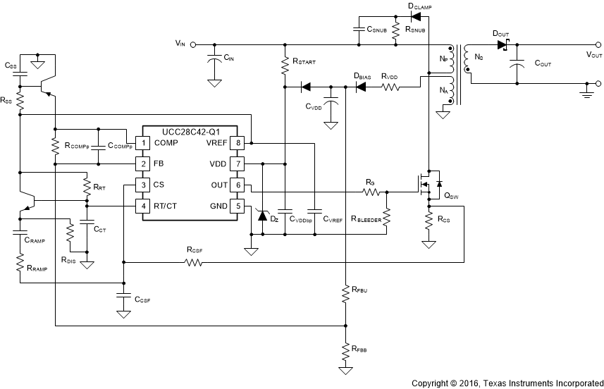
GUID-C6F6B97F-07DF-4B15-8035-8CC09067FEC5-low.gif図 3-1 標準的な車載アプリケーションの例