DLPU103B october 2020 – may 2023 DLP230NP
- 1
- DLP LightCrafter Display 230NP EVM
- Trademarks
- 1 DLP LightCrafter Display 230NP EVM Overview
- 2 Safety Instructions
- 3 Applicable Documents
- 4 What is in the DLP LightCrafter Display 230NP EVM?
- 5 Light Engine
- 6 Quick-Start Procedure
- 7 Connectors on Formatter Board
- 8 EVM Setup
- 9 Raspberry Pi Guide
- 10Troubleshooting
- 11Support Resources
- 12Revision History
6 Quick-Start Procedure
This quick-start assumes the default EVM condition as shipped.
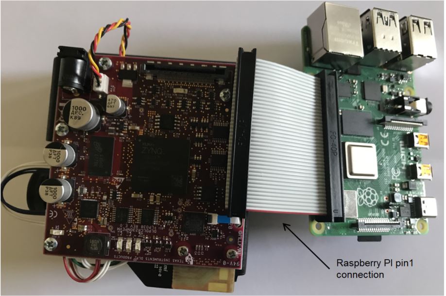
- In case a Raspberry PI is available,
proceed with connecting the DLPDLCR230NPEVM to the Raspberry PI. Ensure that the
Raspberry
Pi has been setup as described in Section 9. If the Raspberry PI
is currently not needed, proceed with step 2.
 Figure 6-1 DLPDLCR230NPEVM With Raspberry
PI
 - Power up the DLP LightCrafter Display
230NP EVM by applying an external DC power supply
(5-V
DC) to the JPWR1 connector.
The D_P5V LED will indicate that the 5-V DC power supply has been
applied to the system.
TI used following power supply for this EVM : ME30A0503F01.
External Power Supply Requirements:- Nominal Output Voltage: 5 VDC
- Minimum Output Current: 4 A
- Efficiency Level: VI
- Output Connector: Barrel Plug, 2.5 mm I.D. × 5.5 mm O.D. × 9.5 mm
- The system will automatically drive Proj-ON high when the 5-V DC power supply is applied and the fan is plugged in. If the fan is not plugged in or a loose connection is present Proj-ON will not be driven high. The DLPDLCR230NPEVM includes a input voltage monitor which drives Proj-ON low if the input voltage drops below approximately 4.65 V for any reason during operation.
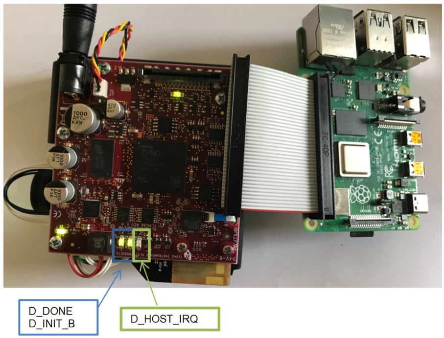
- After the DLP LightCrafter Display
230NP EVM is turned on; the projector will default to displaying a DLP logo followed by
a LightCrafter Display test pattern image. The D_HOST_IRQ will be OFF which indicates a
successful
boot of the DLPC3436. The D_DONE and D_INIT_B will be ON to indicate a successful
boot-up of the FPGA.
 Figure 6-2 DLPDLCR230NPEM LED
Indications
 - The focus of the image can be adjusted
manually on the optical engine.
 Figure 6-3 Optical Engine With Focus
Adjustment
 - Ensure that Raspberry has been configured correctly as described in Section 9 before applying power to the Raspberry PI via the USB Type C cable.
- Power down with the Raspberry PI connected:
- Power down without Raspberry PI
connected:
The projector can be turned off by just removing the power cable. A voltage monitor on the EVM will detect the input voltage go below approximately 4.65 V and will drive Proj-ON low automatically.
There are five indicator LEDs on the DLP LightCrafter Display 230NP EVM, and they are defined in Table 6-1:
Table 6-1 LEDs on the DLP®LightCrafter™ Display 230NP EVM
| LED Reference | Signal Indication | Description |
|---|---|---|
| D_HOST_IRQ | HOST_IRQ | ON during DLPC3436 boot, OFF when projector is running. Indication of DLPC3436 boot-up completed and ready to receive commands |
| D_PROJ_ON | PROJ_ON | PROJ_ON signal is HIGH |
| D_INIT_B | INT_B | ON when FPGA initialization is completed. OFF indicates that the FPGA is in RESET or a configuration error occurred. |
| D_DONE | DONE | ON when FPGA configuration is completed. |
| D_P5V | P5V | Input voltage 5 V applied |