SBAA201A March 2013 – March 2023 ADS1120 , ADS1120-Q1 , ADS1147 , ADS1148 , ADS114S06 , ADS114S06B , ADS114S08 , ADS114S08B , ADS1220 , ADS122C04 , ADS1247 , ADS1248 , ADS124S06 , ADS124S08
1 Introduction
Resistance temperature detectors (RTDs) work by correlating the change of the resistance of a metal sensing element versus a temperature change. As the temperature of the RTD element increases, the electrical resistance of the RTD metal increases. When performing the measurement of a resistive sensor, such as an RTD in data acquisition systems, a constant current source excitation is frequently used.
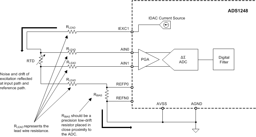
The ADS1148 and ADS1248 family of devices incorporates two programmable current sources that can be used to excite the RTD sensors. Figure 1-1 shows a typical configuration used to measure an RTD in a four-wire configuration.
 Figure 1-1 Four-Wire Ratiometric RTD
Measurement Using the ADS1248
Figure 1-1 Four-Wire Ratiometric RTD
Measurement Using the ADS1248In the simplified circuit diagram shown in Figure 1-1 , the current from the IDAC source flows through the RTD sensor and the return current flows through the RBIAS resistor. The RLEAD resistor represents the lead wire resistance connecting the RTD element, generally limited to 10 Ω or less. The voltage generated across the RBIAS resistor is the voltage reference for the ADC. In addition, the RBIAS resistor places the RTD at a voltage greater than the analog negative supply (AVSS) in order for the sensor to be biased in the valid input common-mode voltage range of the ADC.
ADCs produce an output code as a function of the ratio of the input voltage to the reference voltage. In the ratiometric circuit shown in Figure 1-1, the voltage across the RTD sensor and the RBIAS resistor are generated with the same excitation source. Any changes as a result of the excitation current source drift is reflected across the sensor at the input path of the device, and across the RBIAS resistor at the reference path of the ADC. In this ratiometric configuration, if the RTD and RBIAS resistances remain unchanged, the digital output of the ADC is unaffected by changes of the excitation source.
Performing sensor measurements in a ratiometric configuration provides a significant advantage, where the errors as a result of the absolute accuracy of the excitation current and the errors because of to the excitation drift are virtually eliminated. In addition, when performing measurements in a ratiometric configuration, the noise of the excitation source at the inputs is reflected to the reference path of the ADC; and in this manner, the noise cancels.
In many applications, input RC low-pass filters are employed to improve the end-product immunity to radio frequency interference (RFI) and electromagnetic interference (EMI). However, it is important that the input filter and the reference filter have matched time constants or the cancellation of current source noise can degrade, leading to increasing noise with increasing signal level. Although the ratiometric circuit can work without the use of external RC filters, the addition of low-pass RC filters may prove to be beneficial in noisy environments, where the sensor circuit is prone to noise interference. This document focuses on maintaining noise cancellation of the current source when external RC filters are used.