SBAA217 July 2016 OPT8241 , OPT8320 , OPT9221
3.3 Centering
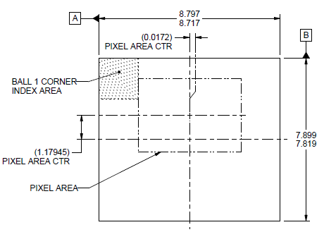
The sensor need not have its optically-active pixel area in the center of the package. For instance, the OPT8241 has its pixel area off-centered.
 Figure 1. OPT8241 Pixel Area
 The lens optical axis has to pass through the pixel area’s center. This might involve using lens holders which have an offset in the lens optical axis. It is also possible to use much larger lens holders which still manage to encompass the sensor package under them.
There might be other components present around the sensor package as well. AC decoupling capacitors and other such components which have to be placed very close to the sensor package will have to be accommodated under the lens holder. The holder has to be chosen or designed for the PCB footprint area taken up by the components as well as the profile height of the components. Some taller components might not fit under the lens holder.
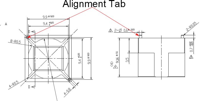
Another important aspect with respect to centering is the centering tolerance of the lens holder. Typical mounting by making use of screws might help center the lens up to a tolerance of ±100 µm. In the OPT8241, 13 pixels are 200 µm. It gets progressively harder to correct for the lens distortions and the mounting tolerances as the centering goes off. Use lens holders with good centering. Sometimes this is done by using alignment tabs.
 Figure 2. Lens Holder
 These alignment tabs get inserted into high precision holes made in the PCB. Unlike screws, these can be made to fit tightly inside the PCB. The alignment tabs give much better centering as compared to screws. Screws will still be useful as an alternative to glue to affix the holder on to the PCB.