SBAU227A March 2014 – June 2021 TPS56520 , TPS56720 , TPS56920 , TPS56C20
3.2.3 Voltage Scaling Procedure
Set voltage scaling by using the following steps:
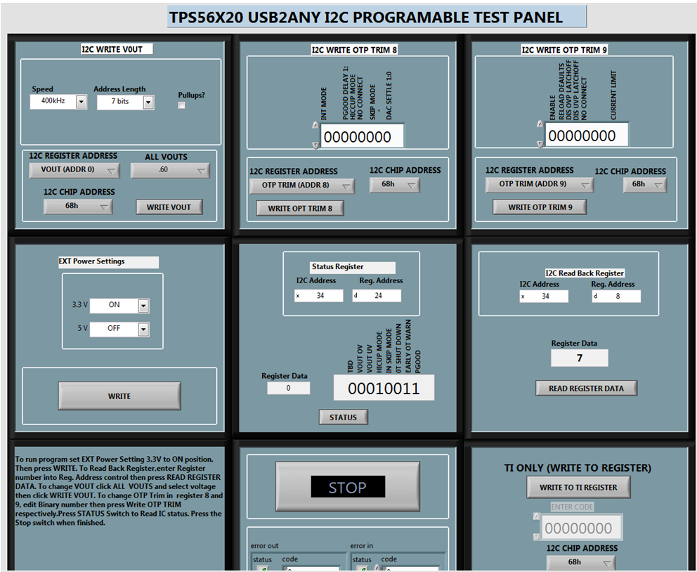
- Go to Program Files and click on the TPS56X20 I2C TEST PANEL Application. The TPS56X20 I2C TEST PANEL will load as shown in Figure 3-2.
 Figure 3-2 TPS56X20 I2C TEST PANEL
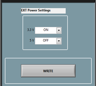
 - As a first step before sending a VOUT command, click the write command On the EXT Power Settings block as shown in Figure 3-3.
 Figure 3-3 EXT Power Settings
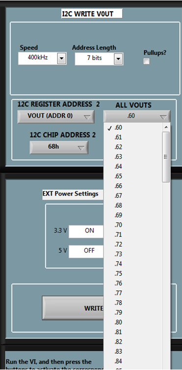
 - Go to the VOUTS control block and click on the ALL VOUTS control, illustrated in Figure 3-4. The drop down menu gives an option to select different VOUT.
 Figure 3-4 ALL VOUTS Control
 - Select a particular value and click on WRITE VOUT switch.
Observe that the Voltage at TP6 relative to TP7 is changed to the programmed VOUT value.