SLAA351A April 2007 – November 2018 MSP430F2232 , MSP430F2232 , MSP430F2234 , MSP430F2234 , MSP430F2252 , MSP430F2252 , MSP430F2254 , MSP430F2254 , MSP430F2272 , MSP430F2272 , MSP430F2274 , MSP430F2274
3.4.1.2 High-Pass Filtering
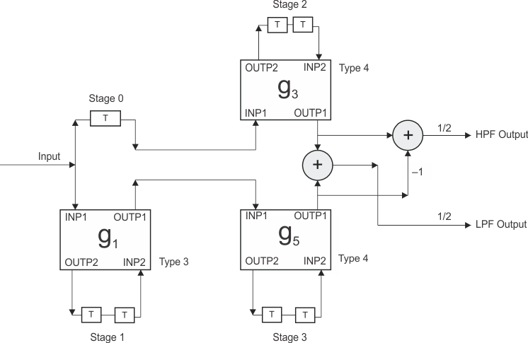
The non-averaged signal is then passed through a high-pass filter with a cutoff set at one-fourth the sampling frequency (9.7 kHz). This is done to remove the low-frequency signals to decide on a glass breakage. The lattice wave digital filter (LWDF) is used to do this filtering. The LWDF is well suited for microcontrollers without a hardware multiplier.[3] The LWDF exhibits excellent stability properties over nonlinear conditions and has a good dynamic range in its coefficients. The bireciprocal filter structure of seventh order is chosen in this application. The LWDF gives one output sample every sample period, and this output is also integrated to facilitate the second stage of processing. Similarly, during this integration, the overflow is considered, and a 32-bit result accommodated. Figure 10 shows the signal flow diagram of the seventh-order bireciprocal LWDF. During the signal analysis, high-pass filtering is done using the LWDF.[5]
 Figure 10. Signal Flow Diagram of a Seventh-Order Bireciprocal LWDF
 The LWDF structure is able to simultaneously give the complimentary output to the HPF with just one extra instruction cycle. The entire filtering operation is done in only 153 instruction cycles. The filter specifications and the resulting coefficients are:
Filter specifications:
Filter response type = High pass
Sampling frequency = 38.960 kHz
3-dB cutoff frequency = 9.74 kHz
Stop-band attenuation = 44 dB
Filter type = Elliptical
Filter structure = Bireciprocal
Filter order = 7
Filter coefficients = –0.109375, –0.375, and –0.75
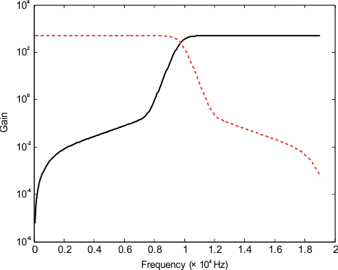
Figure 11 shows the frequency response of this LWDF with its complimentary counterpart.
 Figure 11. Frequency Response of Seventh-Order Bireciprocal LWDF