SLAA534A June 2013 – June 2020
- 1 Introduction
- 2 Data Representation
-
3 Calling Conventions
- 3.1 Call and Return
- 3.2 Register Conventions
- 3.3 Argument Passing
- 3.4 Return Values
- 3.5 Structures and Unions Passed and Returned by Reference
- 3.6 Conventions for Compiler Helper Functions
- 3.7 Scratch Registers for Functions Already Seen
- 3.8 _ _mspabi_func_epilog Helper Functions
- 3.9 Interrupt Functions
- 4 Data Allocation and Addressing
- 5 Code Allocation and Addressing
- 6 Helper Function API
-
7 Standard C Library API
- 7.1 Reserved Symbols
- 7.2 <assert.h> Implementation
- 7.3 <complex.h> Implementation
- 7.4 <ctype.h> Implementation
- 7.5 <errno.h> Implementation
- 7.6 <float.h> Implementation
- 7.7 <inttypes.h> Implementation
- 7.8 <iso646.h> Implementation
- 7.9 <limits.h> Implementation
- 7.10 <locale.h> Implementation
- 7.11 <math.h> Implementation
- 7.12 <setjmp.h> Implementation
- 7.13 <signal.h> Implementation
- 7.14 <stdarg.h> Implementation
- 7.15 <stdbool.h> Implementation
- 7.16 <stddef.h> Implementation
- 7.17 <stdint.h> Implementation
- 7.18 <stdio.h> Implementation
- 7.19 <stdlib.h> Implementation
- 7.20 <string.h> Implementation
- 7.21 <tgmath.h> Implementation
- 7.22 <time.h> Implementation
- 7.23 <wchar.h> Implementation
- 7.24 <wctype.h> Implementation
-
8 C++ ABI
- 8.1 Limits (GC++ABI 1.2)
- 8.2 Export Template (GC++ABI 1.4.2)
- 8.3 Data Layout (GC++ABI Chapter 2)
- 8.4 Initialization Guard Variables (GC++ABI 2.8)
- 8.5 Constructor Return Value (GC++ABI 3.1.5)
- 8.6 One-Time Construction API (GC++ABI 3.3.2)
- 8.7 Controlling Object Construction Order (GC++ ABI 3.3.4)
- 8.8 Demangler API (GC++ABI 3.4)
- 8.9 Static Data (GC++ ABI 5.2.2)
- 8.10 Virtual Tables and the Key function (GC++ABI 5.2.3)
- 8.11 Unwind Table Location (GC++ABI 5.3)
-
9 Exception Handling
- 9.1 Overview
- 9.2 PREL31 Encoding
- 9.3 The Exception Index Table (EXIDX)
- 9.4 The Exception Handling Instruction Table (EXTAB)
- 9.5 Unwinding Instructions
- 9.6 Descriptors
- 9.7 Special Sections
- 9.8 Interaction With Non-C++ Code
- 9.9 Interaction With System Features
- 9.10 Assembly Language Operators in the TI Toolchain
- 10DWARF
- 11ELF Object Files (Processor Supplement)
- 12ELF Program Loading and Linking (Processor Supplement)
- 13Build Attributes
- 14Copy Tables and Variable Initialization
- 15Revision History
14.3 Variable Initialization
As described in Section 4.2, initialized read-write variables are collected into dedicated section(s) of the object file, for example .data. The section contains an image of its initial state upon program startup.
The TI toolchain supports two models for loading such sections. In the so-called RAM model, some unspecified external agent such as a loader is responsible for getting the data from the executable file to its location in read-write memory. This is the typical direct-initialization model used in OS-based systems or, in some instances, boot-loaded systems.
The other model, called the ROM model, is intended for bare-metal embedded systems that must be capable of cold starts without support of an OS or other loader. Any data needed to initialize the program must reside in persistent offline storage (ROM), and get copied into its RAM location upon startup. The TI toolchain implements this by leveraging the copy table capability described in Chapter 14. The initialization mechanism is conceptually similar to copy tables, but differs slightly in the details.
Figure 14-3 depicts the conceptual operation of variable initialization under the ROM model. In this model, the linker removes the data from sections that contain initialized variables. The sections become uninitialized sections, allocated into RAM at their run-time address (much like, say, .bss). The linker encodes the initialization data into a special section called .cinit (for C Initialization), where the startup code from the run-time library decodes and copies it to its run address.
 Figure 14-3 ROM-Based Variable Initialization Via cinit
Like copy tables, the source data in the .cinit tables may or may not be compressed. If it is compressed, the encoding and decoding scheme is identical to that of copy tables so that the handler tables and decompression handlers can be shared.
The .cinit section contains some or all of the following items:
- The cinit table, consisting of cinit records, which are similar to copy records.
- The handler table, consisting of pointers to decompression routines, as described in Section 14.2. The handler table and handlers are shared by initialization and copy tables.
- The source data, consisting of compressed or uncompressed data used to initialize variables.
These items may be in any order.
Figure 14-4 is a schematic depiction of the .cinit section.
 Figure 14-4 The .cinit Section
The .cinit section has the section type SHT_TI_INITINFO which identifies it as being in this format. Tools should rely on the section type and not on the name .cinit.
Two special symbols are defined to delimit the cinit table: __TI_CINIT_Base points to the cinit table, and __TI_CINIT_Limit points one byte past the end of the table. The startup code references the table using these symbols.
The format of the CINT_RECORD structure depends on the code and data model being used.
For the small data model and small code model:
        typedef struct  {
           void  * source_data; /* 16-bit pointer */
           void  * dest;        /* 16-bit pointer */
        } CINIT_RECORD;
For the small data model and large code model:
        typedef struct  {
           uint32  source_data; /* 32-bit storage for data or code pointer */
           uint32  dest;        /* 32-bit storage for data or code pointer */
        } CINIT_RECORD;
For the large (or restricted) data model and large code model:
        typedef struct  {
           void  * source_data; /* 20-bit pointer */
           void  * dest;        /* 20-bit pointer */
} CINIT_RECORD;- The source_data field points to the source data in the cinit section.
- The dest field points to the destination address. Unlike copy table records, cinit records do not contain a size field; the size is always encoded in the source data.
The source data has the same format as compressed copy table source data (see Section 14.2), and the handlers have the same interface. In addition to the RLE and LZSS formats, there are two additional formats defined for cinit records: uncompressed, and zero-initialized.
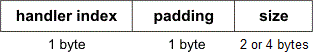
- The explicit uncompressed format is required because unlike a copy table record, there is no overloaded size field in a cinit record. The size field is always encoded into the source data, even when no compression is used. The encoding is as follows:

The encoded data includes a size field, which is aligned on the next 2-byte boundary following the handler index. The size of the "size" field depends on the memory model. For the small code and small data model, the size is 2 bytes. In all other memory model combinations, the size is 4 bytes. The size field specifies how many bytes are in the data payload, which begins immediately following the size field. The initialization operation copies sizebytes from the data field to the destination address. The TI run-time library contains a handler called _ _TI_decompress_none for the uncompressed format.
- The zero-initialization format is a compact format used for the common case of variables whose initial value is zero. The encoding is as follows:
The size field is aligned on the next 2-byte boundary following the handler index. The size of the "size" field depends on the memory model. For the small code and small data model, the size is 2 bytes. In all other memory model combinations, the size is 4 bytes. The initialization operation fills size consecutive bytes at the destination address with zero. The TI run-time library contains a handler called _ _TI_zero_init for this format.
As an optimization, the linker is free to coalesce initializations of adjacent objects into single cinit records if they can be profitably encoded using the same format. This is typically significant for zero-initialized objects.