SLAAE71 December 2022 MSPM0G1105 , MSPM0G1106 , MSPM0G1107 , MSPM0G1505 , MSPM0G1506 , MSPM0G1507 , MSPM0G3105 , MSPM0G3106 , MSPM0G3107 , MSPM0G3505 , MSPM0G3506 , MSPM0G3507
- Abstract
- Trademarks
- 1Overview
- 2Low-Power Features in PMCU
- 3Low-Power Optimization
- 4Power Consumption Measurement and Evaluation
3.1 Low-Power Basics
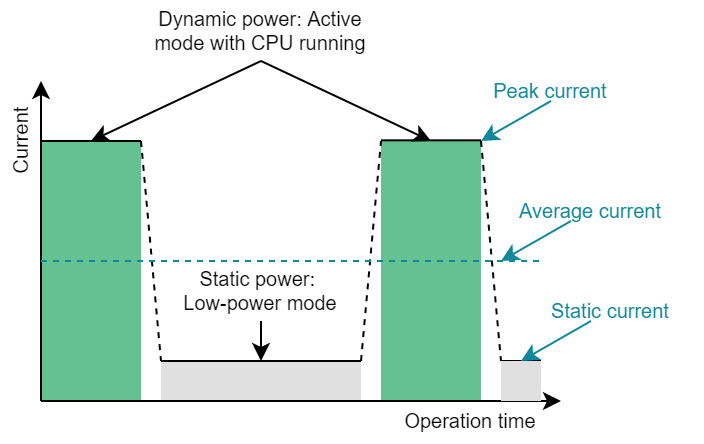
Before describing how to optimize the power consumption, the following helps the reader to know some basic concept about low power. In MCUs, the power consumption mostly comes from 2 parts: dynamic power and static power (see Figure 3-1).
 Figure 3-1 Power Consumption Demonstration
Dynamic power
Dynamic power refers to the current when the CPU and most peripherals are running. This is the highest current during the whole operation time, which is called peak current. Power sources can be CPU, flash, RAM, power management unit (PMU), digital peripherals, and analog peripherals. Dynamic power can generally be divided into the current when switching CMOS circuits and the bias current of analog circuits.
Due to the structure of CMOS inverters, the power consumption mainly occurs when the input voltage is switched. This power can be described by the following equation. U is the system voltage, f is the switching frequency, and C is the load capacitance.
From the equation, there are two methods to help improve the dynamic power, considering that the load capacitance cannot be changed. The first is to reduce the system voltage, which is very helpful, but it is limited by the working voltage range of the MSPM0. The designer also needs to check the working voltage of peripherals, which may be higher than the minimum working voltage of the MCU. In addition, some voltage margin should be left for the power supply.
Second, reduce the system frequency. However, this is usually not a good method because a high working frequency requires less working time but the power caused from bias current increases. Usually, the best choice is to complete the task quickly and return to a low-power mode.
Static power
Static power consumption mainly refers to the bias current and leakage current of analog circuit and digital circuit when CPU and most peripheral devices are turned off. This will be the lowest current during the whole operation time, which is called quiescent current.
In this mode, analog circuits, such as system controller, PMU and IOs, as well as digital circuits, such as real-time clock (RTC) and watchdog timer, need a certain amount of bias current to maintain the basic functions and wake-up possibility. The best strategy is to turn off unused modules and pair them with the suitable operation frequency and appropriate MCU operation mode.
Leakage current is caused by the non-ideal operation of the MOSFETs used in CMOS devices, especially when the process technology shrinks. Leakage current increases with higher power supply and operating temperature. This part of power consumption depends on the MCU you choose.
Optimization directions
For some applications, the most cared part is the peak current. It may lie on the limited current supply, like 4-20mA current loop application or the designer wants to fully use the battery capacity, because large current will reach the terminated voltage faster. The focus optimization direction should be the dynamic power range and decrease the peak current.
For most applications, especially for battery implement, the most cared current is the average current, which defines how long the system can operate. The optimization direction should reduce the dynamic power range, peck current and static current. The equation is shown below. The current in that equation means the average current.
As it is not easy to get the average current in different modes, for the more accurate low-cost method, refer to Section 4.2.