SLAU857A May 2021 – July 2021 MSP430FR2476 , MSP430FR2512 , MSP430FR2522 , MSP430FR2532 , MSP430FR2533 , MSP430FR2632 , MSP430FR2633 , MSP430FR2672 , MSP430FR2673 , MSP430FR2675 , MSP430FR2676
5.6.3 Customization of Communication Functions
It is recommended to use the provided UART and I2C library functions for development to communicate with the host MCU. First of all, the default code generated by the GUI completes the I/O configuration and clock configuration of UART (eUSCI_A0) and I2C (eUSCI_B0) in the BSP_configureMCU() function. Therefore, it is only necessary to configure the communication module and write the communication protocol. If you need to modify the communication interface, check the datasheet to see if you need to modify the SYSCFG3 register to redirect the communication port.
UART-based communication development:
- Communication Interface configuration: NONE
- Clock configuration: BSP_configureMCU()
- IO configuration: BSP_configureMCU()
- UART peripheral configuration and interrupt usage: Driverlib UART loopback
- Comment:
- Baud rate parameter configuration tool: MSP430 USCI/EUSCI UART Baud Rate Calculation
- See the frequency of different system clock sources at captivate_app->CAPT_BSP.h
- Comment:
There are two schemes for I2C-based communication development for reference. The scheme occupies less code, and the second scheme saves development time.
Option one:
- Communication Interface configuration: NONE
- Clock configuration: BSP_configureMCU()
- IO configuration: BSP_configureMCU()
- I2C peripheral configuration and interrupt usage: Driverlib I2C salveTxMultiple, Driverlib I2C salveRxMultiple
Option two★:
- User Guide:I2C Slave driver user guide
- Communication Interface configuration: NONE
- Clock configuration: BSP_configureMCU()
- IO configuration: BSP_configureMCU()
- I2C peripheral configuration and interrupt usage: The code under the REGISTER_I2C configuration includes I2C peripheral configuration and interrupt usage. The user only needs to analyze the 3-byte transmit and receive Buffer. The operation steps are as follows:
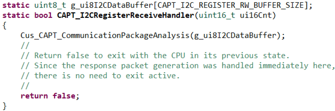
- Modify the CAPT_I2CRegisterReceiveHandler() function in captivate->COMM->CAPT_Interface.c. This function is called when the stop signal or restart signal are generated after the I2C write operation is completed. As shown in Figure 5-16, delete other codes and add custom frame processing functions.
 Figure 5-16 CAPT_I2CRegisterReceiveHandler() Function Modification
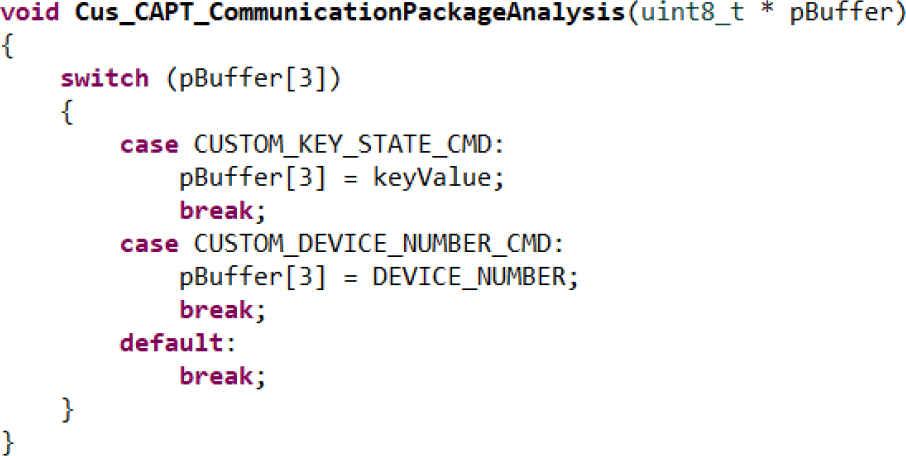
 - Write a custom frame processing function. As shown in Figure 5-17, the MSP430 MCU reads a byte sent by the host, then modify the first byte of the data segment in the Buffer, and then wait for the host to actively read the byte. It should be noted that I2C sending and receiving share a 32-byte buffer, and the whole process does not reset it. In addition, the receiving/sending data segment in the buffer has an offset of 3 bytes. Therefore, the fourth byte of the Buffer corresponds to the first byte of the received/sent data.
 Figure 5-17 Frame Processing Function
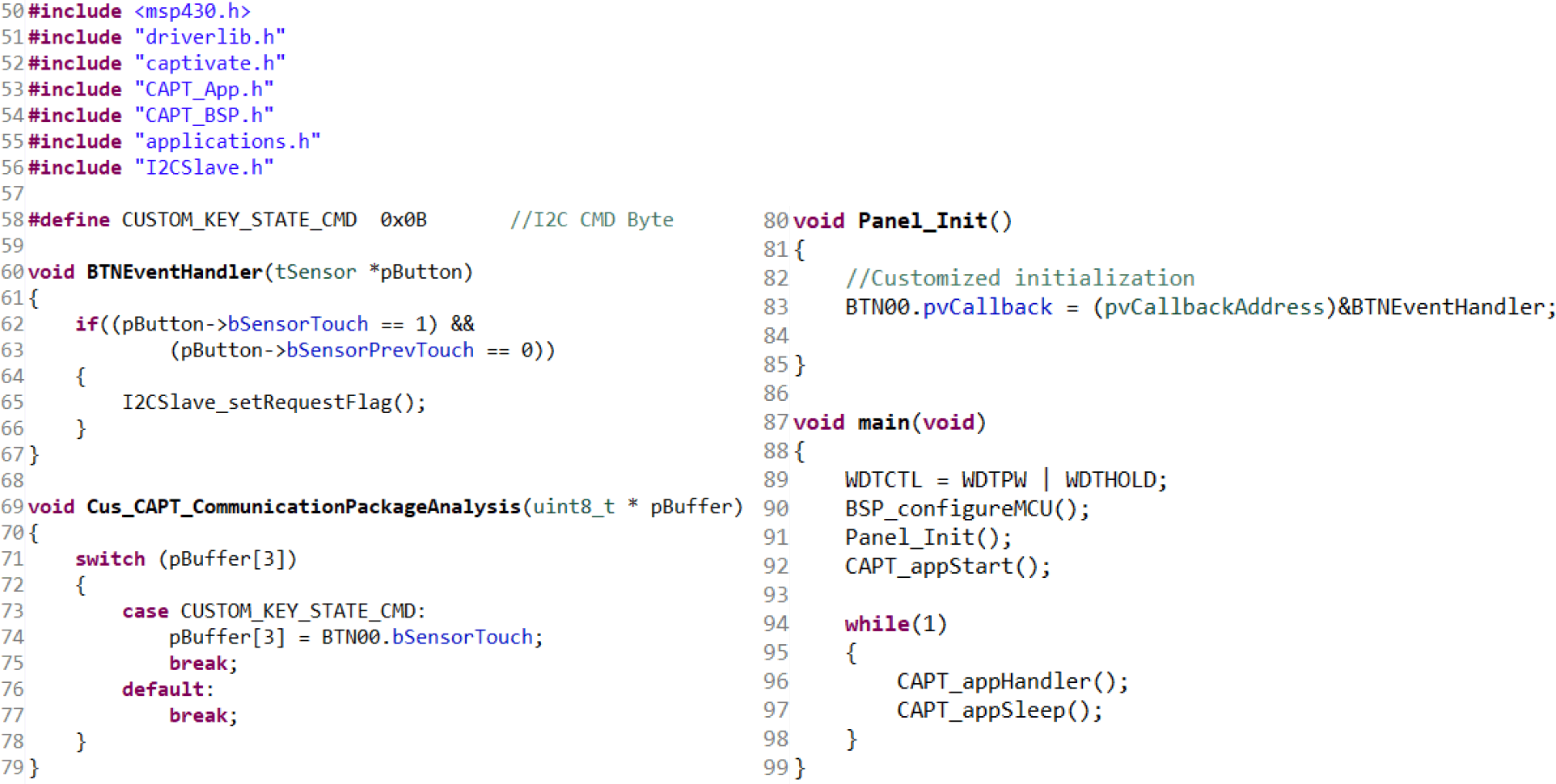
 - Build the overall code as shown in Figure 5-18. The additional functions included are:
- Panel_Init(): System custom initialization, register the sensor callback function.
- BTNEventHandler(): The processing function that defines the state of the sensor.
 Figure 5-18 Diagram of the Overall Code
Table 5-13 shows the information related to the custom communication function.
| Number | Object | Modification method | Comment |
|---|---|---|---|
| 1 | eUSCI_A0/eUSCI_B0 port | Modify the pin definition in Captivate_app->CAPT_BSP.C->BSP_configureMCU() | Select other communication peripherals, need to modify the initialization of the peripherals. |
| 2 | IRQ signal of I2C | Modify the macro definition of IRQ pin in Captivate->COMM->CAPT_CommConfig.h Modify the macro definition of IRQ pin action in Captivate->COMM->I2CSlave.h | This pin is used to remind the host computer of a touch event. |
| 3 | Whether the CapTIvate module enables the Timer peripheral | Modify the assignment of FUNCTIONTIMER__ENABLE in CapTIvate->COMM->FunctionTimer.h | Used for timeout function in I2C communication. |
| 5 | Timeout function of I2C communication | Modify the assignment of I2CSLAVE__TIMEOUT_ENABLE in Captivate->COMM->I2CSlave_Definitions.h Modify the assignment of I2CSLAVE__TXFR_TIMEOUT_CYCLES in Captivate->COMM->I2CSlave_Definitions.h | By default, the host resets I2C if a single frame transmission exceeds 8 ms. |
| 5 | Modify I2C address | Modify I2CSLAVE__ADDRES in CapTIvate->COMM->I2CSlave_Definitions.h |