SLLA618 October 2023 ATL431 , ATL431LI , TL431 , TL431LI , TLVH432
1 Introduction
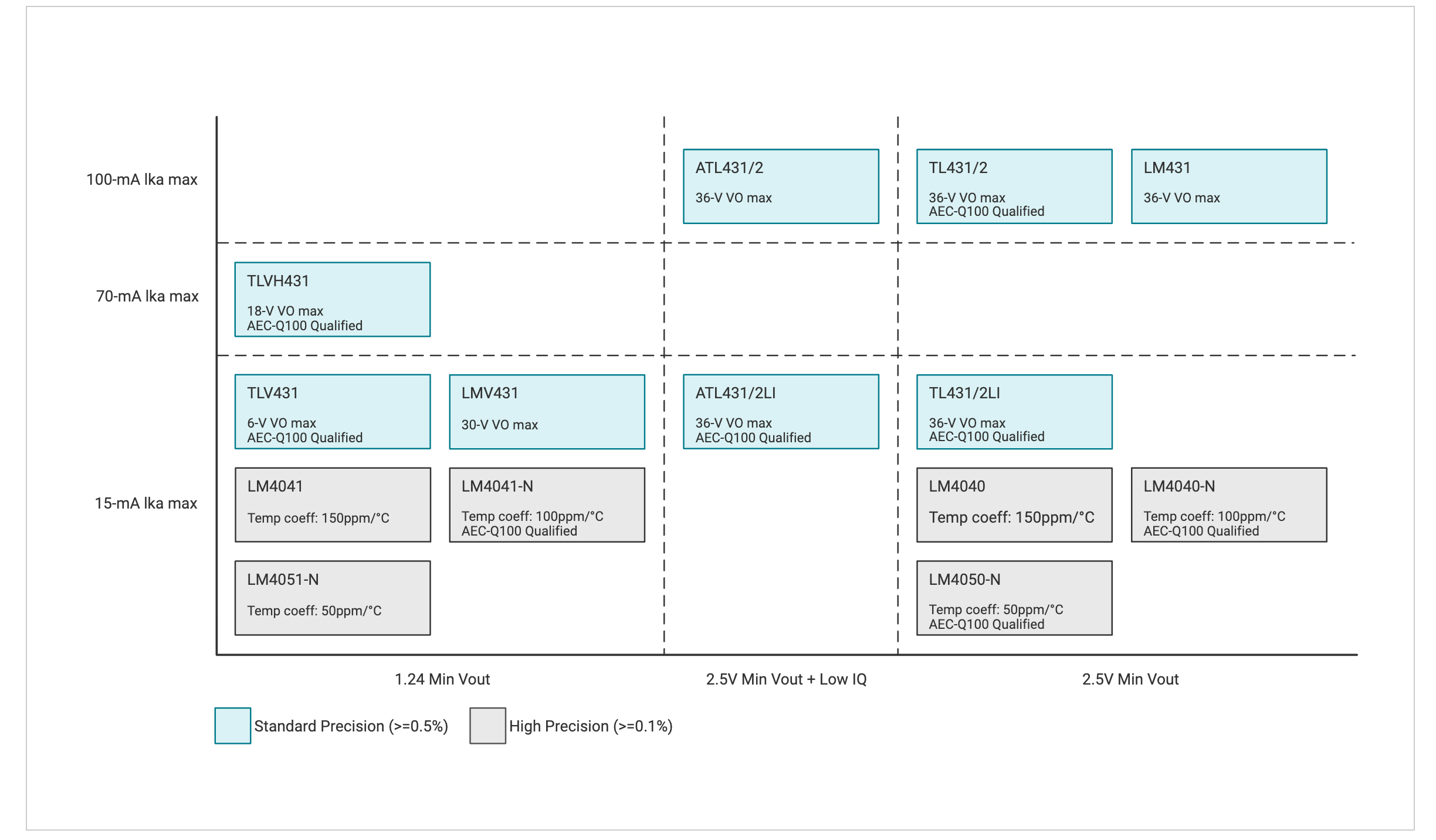
Flyback converters are widely used in power adapters for personal electronics. These AC/DC or DC/DC converters provide the advantage of electrical isolation due to an isolation transformer, which protects end equipment from voltage surges and ground loops. The key elements of a flyback converter include a feedback network, PWM controller, gate driver IC, and switching MOSFETs. A flyback converter uses either primary-side regulation (PSR) or secondary-side regulation (SSR) to provide feedback to the PWM controller to set the output voltage. SSR provides the advantages of a quick transient response, reduced noise coupling between the primary and secondary sides, and improved accuracy across all load conditions with the disadvantage of an increased component count. SSR implementation requires an optocoupler and a shunt reference acting as an error amplifier in the feedback network of the flyback converter. When selecting this shunt reference for the feedback network, designers must balance accuracy, power dissipation, and transient response requirements. Once this shunt reference is selected, the flyback converter must be configured as an error amplifier to set the flyback converter's output voltage properly. This shunt references performance, and proper biasing can optimize power dissipation. Figure 1-1 shows a list of popular shunt references for designer needs.
 Figure 1-1 Shunt Reference Chart