SLUA863C January 2018 – September 2023 UCC21710-Q1 , UCC21732-Q1 , UCC21750
Silicon Carbide (SiC) MOSFET has become the potential substitute for Silicon (Si) IGBT for various applications such as solar inverters, on-board and off-board battery chargers, traction inverters, and so forth. Comparing it Si IGBT, SiC MOSFET has more stringent short circuit protection requirements. To make the most use of SiC MOSFET and ensure a robust system operation, a fast and reliable short circuit protection circuit is needed. Different characteristics of SiC MOSFET and Si IGBT are discussed, three short circuit protection methods are illustrated and compared, and the requirements of short circuit protection for SiC MOSFETs are summarized. TI’s UCC217xx family, a single-channel isolated gate driver for IGBT and SiC with advanced protection feature, can be used in various system designs to protect the switch from all types of overcurrent and short circuit faults. The best in-class fast protection and high-noise immunity improve the versatility of system design and robustness of the system.
The best way to use the SiC MOSFET is to fully understand the device characteristics. The different characteristics of SiC MOSFET and Si IGBT have an impact on their short circuit protection schemes.
Compared to IGBT, which has similar blocking voltage and current rating, SiC MOSFET has a smaller chip area, which makes the parasitic capacitance smaller than IGBT and increases the intrinsic switching speed. However, the smaller chip area means the SiC MOSFET die has lower thermal dissipation capability. During short circuit conditions, the surge current generates a significant amount of joule heating and the die can be destroyed in a short period of time without enough capability to dissipate the heat. With a smaller die size, the surge current capability of SiC MOSFET is lower than that of IGBT.
The output characteristics of SiC MOSFET and IGBT are different too. IGBT typically works in the saturation region during the normal ON state. When a short circuit happens, the collector current IC increases and goes through a sharp transition from the saturation region to the active region. The collector current gets self-limited and becomes independent of VCE. Consequently, the increase in IGBT current and power dissipation become self-limited.
On the other hand, SiC MOSFET works in the linear region during normal ON operation. During a short circuit event, the SiC MOSFET enters the saturation region. Different than that of an IGBT, SiC MOSFET has a larger linear region. The transition from the linear region to saturation region happens at a significantly higher VDS. The drain current keeps increasing along with the increasing Vds. The device is destroyed before reaching the transition point. These characteristics make the short circuit protection for SiC MOSFETs very different than IGBT.
Short Circuit Protection Methods Comparison
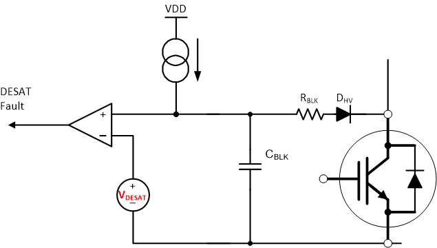
The short circuit protection is important to ensure a robust system and best use of the device. A qualified short circuit protection circuit should realize a fast detection and shut down the device without false trigger. Three short circuit protection schemes which are commonly used today will be analyzed and compared, including desaturation detection, shunt resistor sensing scheme, and senseFET current sensing scheme. The desaturation detection circuit is shown in Figure 1.
 Figure 1 Desaturation Detection
Circuit
Figure 1 Desaturation Detection
CircuitThe circuit consists of a resistor, a blanking capacitor, and a diode. When the device turns on, a current source charges the blanking capacitor and the diode is conducted. During normal operation, the capacitor voltage is clamped at the forward voltage of the device. When short circuit happens, the capacitor voltage is quickly charged to the threshold voltage which triggers the device shutdown. The capacitor charging time is called the blanking time, which is calculated as:

For IGBT, the desaturation threshold voltage is normally set around the transition voltage, as the current can be virtually limited afterward for IGBT to withstand a longer period of time. It needs more attention to design the desaturation circuit for a SiC MOSFET. The blanking time designed for IGBT is too long to protect SiC MOSFET. On one hand, the transition voltage of SiC MOSFET is normally very high, so the current cannot be limited. With the preferred short circuit shutdown time less than 2 µs, the desaturation threshold voltage needs to be set lower. On the other hand, the fast switching speed of the SiC MOSFET generates noise during turnon transition. The short circuit detection time should be designed long enough to avoid the false trigger, which makes the desaturation circuit design challenging for the SiC MOSFET.
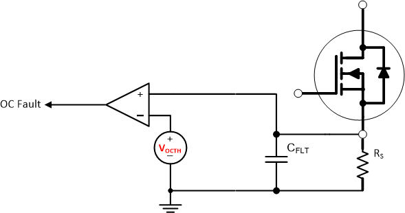
The shunt resistor sensing scheme is shown in Figure 2. A small resistor is connected in series in the power loop to sense the current. This scheme is straight forward and can be flexibly adopted in any system. A high precision resistor and fast ADC are needed to guarantee the accuracy of the signal and detection time. The drawback of this method lies in the power loss. In a high power system, high current generates large power loss on the shunt resistor. In a low power system, larger resistance is needed to ensure the accuracy of the sensing signal, which also generates loss and reduces efficiency in low power applications.
 Figure 2 Shunt Resistor Current Sensing
Scheme
Figure 2 Shunt Resistor Current Sensing
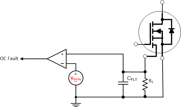
SchemeThe senseFET current sensing scheme is shown in Figure 3. The senseFET is normally integrated in the power module, connecting in parallel with the main device to scale down the device current. The scaled down current is then measured by an accurate shunt resistor. The detection time is short as the sensed current is synchronous with the device current. As the senseFET is integrated in the power module, low noise will be generated due to the small parasitic inductance. Although this scheme has many advantages, a power module with senseFET is required, which increases the system cost.
 Figure 3 SenseFET Current Sensing
Scheme
Figure 3 SenseFET Current Sensing
SchemeSummary
SiC MOSFET is a promising substitute for IGBT in order to achieve a more compact and efficient system. A short circuit scheme for SiC MOSFET should be evaluated from the following aspects: fast response time, low power loss, high accuracy, high noise immunity, and low cost. Efforts should be made from the protection circuits, gate driver, and PCB layout to improve the overall performance. The UCC217XX family has the best in-class overcurrent and short circuit protection feature. With the short detection time and fault reporting time, the gate driver can shut down the IGBT and SiC MOSFET module promptly after fault happens, and report the fault to the isolated input side. The UCC217XX family supports all three detection schemes above, which makes the driver versatile to various system designs. The driver provides a reliable protection for overcurrent and short circuit fault, and increases the robustness of the system.