SLUAAI3 January 2022 TPS62810-Q1 , TPS62811-Q1 , TPS62812-Q1 , TPS62813-Q1 , TPS62816-Q1 , TPS628501 , TPS628501-Q1 , TPS628502 , TPS628502-Q1 , TPS628503 , TPS628503-Q1 , TPS628510 , TPS628511 , TPS628512 , TPS62870 , TPS62870-Q1 , TPS62871 , TPS62871-Q1 , TPS62872 , TPS62872-Q1 , TPS62873 , TPS62873-Q1 , TPS62874-Q1 , TPS62875-Q1 , TPS62876-Q1 , TPS62877-Q1 , TPS62A01 , TPS62A01A , TPS62A02 , TPS62A02A , TPS62A06 , TPS62A06A , TPSM82810 , TPSM82813 , TPSM8287A06 , TPSM8287A12 , TPSM8287A15
5 PDN Impedance Measurement Example
Passive components can help lower the impedance at specific frequencies between power and ground planes. Using a congregate of different passive components on a PDN builds a filter to achieve a target impedance. Usually, on-board passive components lower impedances up to hundreds of MHz.
However, every passive component has parasitic elements influencing its impedance behavior. Analyzing the PDN impedance can help identify critical points of a PDN over frequency. For instance, when applying this to noise elimination, one can verify the effects of using a low impedance capacitor at a given frequency.
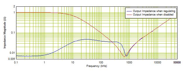
 Figure 5-1 Output Impedance Measurements of the TPS62A01 Connected to a Resistive Load
Figure 5-1 shows the output impedance of the TPS62A01 when the converter is regulating (blue curve) and when the converter is disabled (red curve). In the middle section, the measured impedance tracks the impedance of the output capacitor bank, flattening out with its ESR value at 800 kHz. At high frequency, the impedance is dominated by the inductive behavior of the capacitance.