SLUP409B April 2022 – April 2024 TPS543320 , TPS543620 , TPS543820 , TPS62913 , TPS62916
- 1
- Abstract
- 1 Introduction
- 2 DC/DC Converters are Noisy
- 3 Power-Supply Output Voltage Ripple and Noise Degrade ADC Performance
- 4 Minimizing Low-Frequency Noise Requires Dedicated Low-Noise IC Technologies
- 5 Traditional Approaches to Reducing Ripple
- 6 Using Smaller Capacitors in Parallel
- 7 Larger Inductance
- 8 Adding a Feedthrough Capacitor
- 9 Adding a Ferrite Bead
- 10Layout Techniques
- 11Silicon Solutions
- 12Conclusions
8 Adding a Feedthrough Capacitor
The next set of modifications inserts another stage of output filtering. Our first example creates a second-stage filter with a feedthrough capacitor. Figure 17 shows the modified schematic, with a red box indicating the location of the feedthrough capacitor. This modification includes moving one of the 22-µF ceramic capacitors (originally placed near the inductor) after the feedthrough capacitor to maximize capacitance at the load. Connecting the feedback for the TPS543620 control loop after the feedthrough capacitor offers the best output regulation.
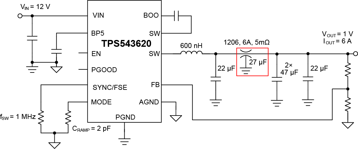 Figure 17 The TPS543620 EVM with a
feedthrough capacitor.
Figure 17 The TPS543620 EVM with a
feedthrough capacitor.A feedthrough capacitor is a three-terminal ceramic capacitor designed to give low equivalent series inductance (ESL). Reducing the ESL results in low impedance across a wider range of frequencies than a conventional ceramic capacitor.
Figure 18 shows what feedthrough capacitors look like. There is an input terminal, an output terminal and a ground terminal in the middle. This terminal configuration results in low ESL.
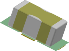
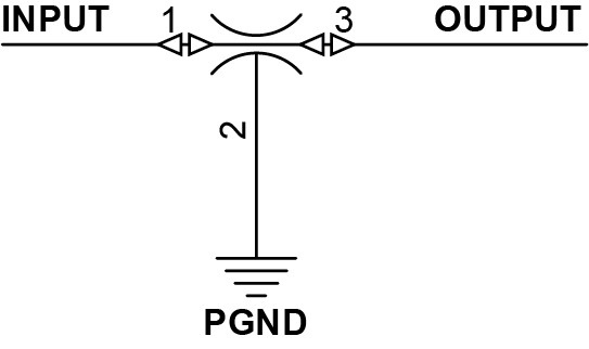 Figure 18 Feedthrough capacitor.
Figure 19 shows the impedance of a 27-µF feedthrough capacitor compared to a conventional 22-µF capacitor. This comparison offers three important observations:
- The feedthrough capacitor has a higher self-resonant frequency as a result of the reduced ESL.
- The minimum impedance is lower than the standard capacitor.
- The impedance stays low across a frequency range from approximately 3MHz to almost 20MHz.
These three effects combined result in less than one-tenth the impedance of the conventional ceramic capacitor above 2MHz.
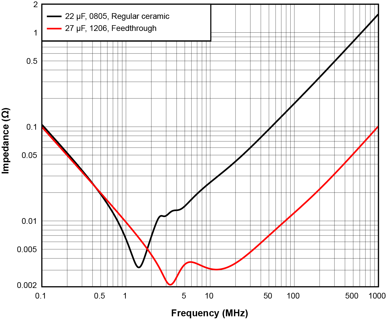 Figure 19 Impedance of a feedthrough
capacitor vs. a standard ceramic capacitor.
Figure 19 Impedance of a feedthrough
capacitor vs. a standard ceramic capacitor.Figure 20, Figure 21 and Figure 22 show the results of adding the feedthrough capacitor. The improved filtering across the entire frequency range is clearly visible in the output ripple. The total ripple, including the high-frequency switching noise, is less than 10mVp-p. Adding the feedthrough capacitor slightly improves the transient response because there is more capacitance on the output.
Figure 22 clearly shows significant reductions in the peaks at each frequency. The reduction of ripple at the 1-MHz fundamental, however, is only approximately one-half, because as Figure 19 shows, the feedthrough capacitors have about the same impedance as the conventional capacitor at 1MHz. Even though the impedance to ground is about the same, the feedthrough capacitor does still provide some additional attenuation at 1MHz because it is inserted in series with the output.
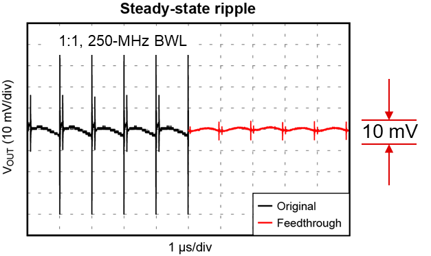 Figure 20 Feedthrough capacitor output
ripple.
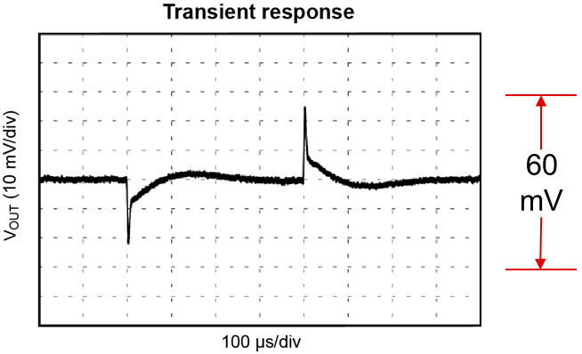 Figure 21 Feedthrough capacitor
transient response.
 Figure 22 Feedthrough capacitor output
FFT.
Figure 22 Feedthrough capacitor output
FFT.Feedthrough capacitors are an effective and simple way to achieve very low ripple, but they have potentially significant trade-offs:
- A feedthrough capacitor is not a standard component, so there are a limited number of vendors and options for different values.
- The device used in our measurements was rated for only an 85°C junction temperature. Higher-ambient-temperature applications require a capacitor with a higher junction temperature rating, but at the time of this writing, the only feedthrough capacitors available with higher ratings have lower capacitance.
- Adding a feedthrough capacitor will add losses caused by conduction losses in its DCR.
- The ripple at the fundamental frequency only dropped approximately in half, so more filtering at the fSW may be required to achieve ripple below 1mV. More filtering at the fSW typically requires a feedthrough capacitor with more capacitance and a self-resonant frequency near the fSW, but again, there are not any such capacitors available at this time.