SLUUBS4A January 2018 – June 2021 TPSM84209
2 Getting Started
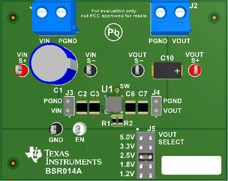
Figure 2-1 highlights the user interface items associated with the EVM. The VIN Power terminal block (J1) is used for connection to the host input supply and the VOUT Power terminal block (J2) is used for connection to the load. These terminal blocks can accept up to 16-AWG wire.
 Figure 2-1 TPSM84209 EVM User Interface
The S+ and S- test points for both VIN and VOUT, located near the power terminal blocks are intended to be used as voltage monitoring points where voltmeters can be connected to measure VIN and VOUT. Do not use these S+ and S- monitoring test points as the input supply or output load connection points. The PCB traces connecting to these test points are not designed to support high currents.
The VIN Scope (J3) and VOUT Scope (J4) test points can be used to monitor VIN and VOUT waveforms with an oscilloscope. These test points are intended for use with un-hooded scope probes outfitted with a low-inductance ground lead (ground spring) mounted to the scope probe barrel. The two sockets of each test point are on 0.1 inch centers. The scope probe tip must be inserted into the socket marked with a white dot, and the scope ground lead must be inserted into the other socket.
The Enable (EN) and ground (GND) test points located to the left of the device are made available to enable or disable the device. Leaving the EN test point floating enables the device when a valid input voltage is applied, while connecting EN to GND disables the device. Refer to the Test Points Descriptions section of this guide for more information on the individual control test points.
The VOUT SELECT jumper (J5) is provided for selecting the desired output voltage. Before applying power to the EVM, ensure that the jumper is present and properly positioned for the intended output voltage. Always remove input power before changing the jumper setting.