SLVA488B January 2014 – January 2021 DRV8434 , DRV8811 , DRV8818 , DRV8821 , DRV8824 , DRV8825
2.2 Accelerating the Motor
The start stepper command starts by issuing steps at a starting frequency denoted by the StartingSpeed variable. A timer must be used to generate STEP pulses at such frequency. On this application note, Timer A0.2 was used to set the STEP signal and Timer A0.0 was used to clear the same signal. The pulse width is 32 clock pulses wide which translates to 2 µs. Since the DRV8825 requires STEP pulses at least 1-µs wide, this implementation results in a legal pulse generation.
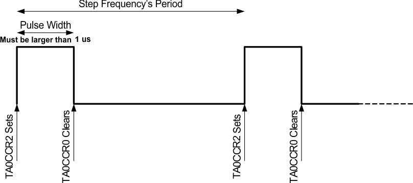 Figure 2-2 Timer A0 Used to Generate STEP Pulses
The interrupt subroutine for Timer A0.2 is in charge of programming the Timer A0.0 hardware reset, as well as programming itself in order to schedule the next step generation.
A second timer function is needed to generate the acceleration portion of the speed control profile. The microcontroller selected for this application only had two available timers so as will be explained shortly, a trade off had to be made.
Timer A1.1 was used along with timer A1.0 to generate the PWM output which would be used to generate an analog to digital converter, by adding an RC filter, to drive the DRV8825’s VREF analog input pin. With this technique, it is then possible to control stepper current in real time.
Although all timer resources seem to be depleted, there is still an aspect of timer A1 we can utilize. If we code the PWM generator to count from decimal 0 to decimal 249, we will have 250 time units. At 16 MHz, each timer unit is equal to 62.5 ns with 250 of them accounting for 15.625 µs. By further dividing this result by 8, we can get a fairly useful time base of 125 µs, or 4000 timer ticks per second.
What this means is we can increase the stepper speed rate up to 4000 times per second. A simple mathematical equation can then be used to compute both the acceleration time interval and the acceleration increment parameter. The code snippet below shows the equations used to compute both aspects of the acceleration parameter:
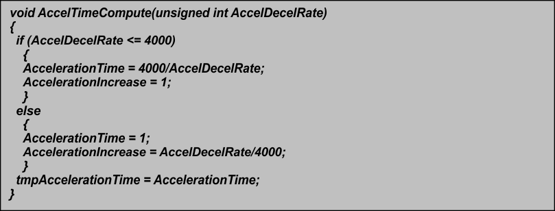 Figure 2-3 Function Computing Time Interval and Acceleration Increase Parameters for Acceleration or Deceleration Rate
Figure 2-4 shows the flowchart of the state machine in charge of coordinating the acceleration. As can be seen, the command to start the motor will configure all the parameters required for motion, including the call to the AccelTimeCompute function.
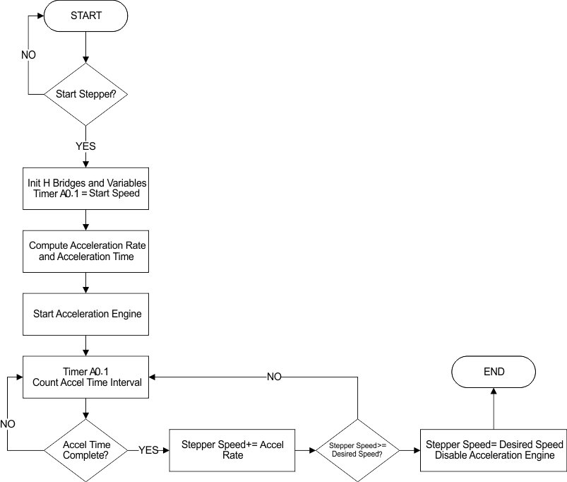 Figure 2-4 Stepper Speed Acceleration Flowchart
The actual speed modification takes place inside the AccelDecel function which gets called from within the main execution which is in turn enabled within the timer A1.0 interrupt service routine (ISR). It is important for the AccelDecel function not to be called from within inside the ISR as this impacts real time operation. Instead, inside the ISR the microcontroller sleep mode is disabled, which allows execution to resume from the main loop.
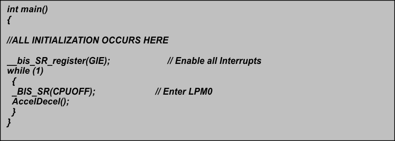 Figure 2-5 Main Function Calls the AccelDecel Code Whenever Code Inside of an ISR Removes the Micro from Sleep Mode
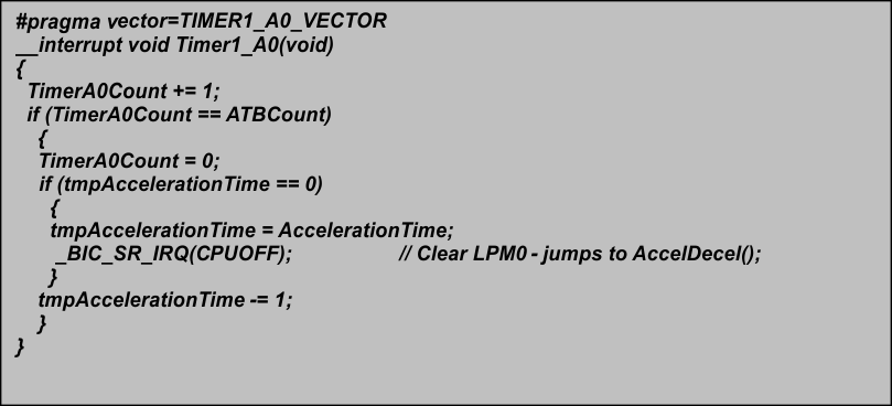 Figure 2-6 Timer A1.0 ISR Disables Sleep Mode Once an Acceleration Tick is to be Executed
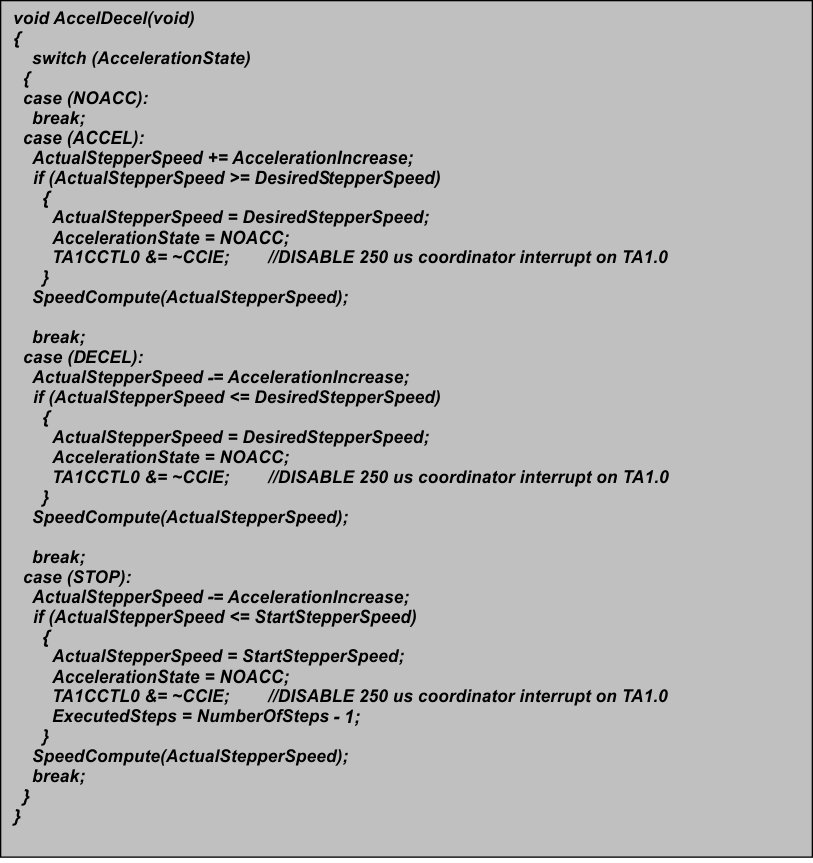 Figure 2-7 AccelDecel Function is State Machine Code in Charge of Modifying Stepper Speed According to Programmed Acceleration or Deceleration Profile