SLVAE51A November 2018 – October 2020 LM7310 , TPS2100 , TPS2101 , TPS2102 , TPS2103 , TPS2104 , TPS2105 , TPS2110 , TPS2111 , TPS2111A , TPS2112 , TPS2112A , TPS2113 , TPS2113A , TPS2114 , TPS2114A , TPS2115 , TPS2115A , TPS2120 , TPS2121 , TPS25947
4.4 Inrush Current
A faster slew rate switch will reduce the switchover time, but will cause a faster dVOUT/dt and therefore a larger spike of inrush current based on the equation:
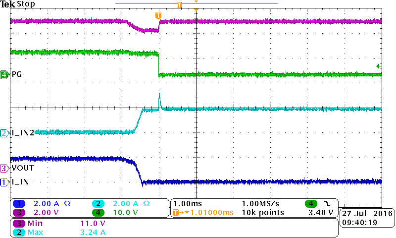
 Figure 4-2 Inrush Current Spike Caused by Supply Switchover
 Figure 4-3 Inrush Current Spike on IN2 During Switchover Using 2x TPS25942
In this example, 2x TPS25942 eFuses were used to form a semi-integrated power MUX solution. The device was initially powered by CH-1, I_IN and then transitioned to CH-2, I_IN2. During the switchover time, output voltage began to drop by a diode drop. Once the switchover passed, there was a peak inrush current spike of approximately 3.42 A in order for the output to recharge. More examples of peak inrush current test results can be found at Power Multiplexing Using Load Switches and eFuses.
There are two variables that can help a designer meet their target output voltage dip versus inrush current performance in a power MUX solution.
- Output Capacitance - Following equations 1 through 4, increasing COUT will cause lower output voltage dip at the expense of higher inrush current during the transition, and vice-versa.
- Switchover Times - Discrete power MUX solutions rely on RC delays in order to limit inrush current. This will result in relatively slow switchover times and relatively high dv/dt as the switch rise time will get exponentially larger as it turns on. In comparison, semi-integrated and fully integrated power MUX solutions often use a controlled linear rise time. This will result in relatively lower amounts of inrush current and a faster switchover time. There will be integrated power MUX solutions available at slew rate and switchover time combinations which are simply not possible with a discrete solution.