SLVAER4 August 2020 – MONTH TPS61022
4.1 Schematic
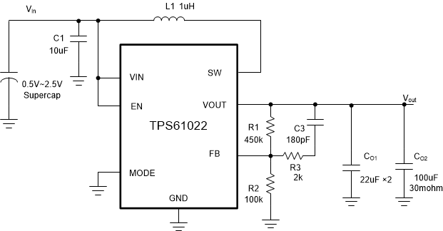
Figure 4-1 shows the schematic for a typical supercap backup power application.
 Figure 4-1 TPS61022 Circuit With Feedfoward
Capacitor
Figure 4-1 TPS61022 Circuit With Feedfoward
CapacitorAlthough a large aluminum polymer capacitor CO2 is used, 1 to 2 multilayer X5R or X7R low ESR, 22-µF ceramic capacitors are also necessary and must be placed close to the VOUT pin and GND pin.
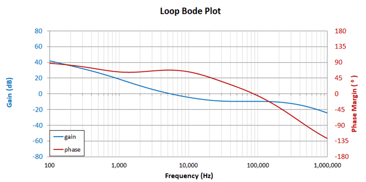
By inputting the parameter shown in Figure 4-1, TPS61022 calculation tool generate the loop bode plot shown in Figure 4-2 for VIN = 0.7 V. The crossover frequency is 5.6 kHz with 67.8° phase margin and 9.5-dB gain margin.
 Figure 4-2 Bode Plot With Recommended
External Components