SLVAEV8 June 2020 DRV8106-Q1 , DRV8701 , DRV8702-Q1 , DRV8702D-Q1 , DRV8703-Q1 , DRV8703D-Q1 , DRV8705-Q1 , DRV8706-Q1
2 Using VDS Monitors to Identify Fault Types
Once the desired specifications for VDS monitoring are set, the device is ready to detect faults. Three reasons an OCP condition occurs is the H-bridge outputs (SHx) are either shorted to ground, shorted to the supply voltage, or shorted to each other. The type of short can be identified depending on which VDS monitor detects the OCP condition.
The short to supply scenario is shown in Figure 2 and Figure 3. In Short to VM Case 1, if the motor were to drive in reverse (only GH2 and GL1 are on) the voltage at SH1 would be VM and the VDS monitor across GL1 would trigger an OCP event. Similarly, in Short to VM Case 2, if the motor were to drive forward (only GH1 and GL2 are on) the VDS monitor across GL2 would detect an OCP condition. In low side brake (only GL1 and GL2 are on) the OCP condition is detected by whichever low side FET is on the same side as the short to supply.
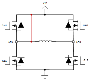 Figure 2. Short to VM Case 1
 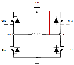 Figure 3. Short to VM Case 2
 The Figure 4 and Figure 5 show the short to ground scenarios. If the motor were to drive forward (only GH1 and GL2 are on) in Short to GND Case 1, the high current through GH1 would trigger that FET’s VDS monitor for an OCP event. Similarly, if the motor were to drive in reverse (only GH2 and GL1 are on) in the Short to GND Case 2 scenario, GH2’s VDS monitor would trigger an OCP event.
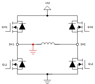 Figure 4. Short to GND Case 1
 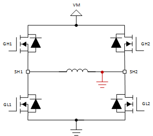 Figure 5. Short to GND Case 2
 Lastly, the SHx pins can be shorted to each other due to poor soldering, poor terminal connections, or a short in the motor windings. In this scenario, the VDS monitors across any driving FET will detect an OCP condition. For example, when driving forward (only GH1 and GL2 are on) the VDS monitors across FETs GH1 and GL2 will detect an OCP condition.
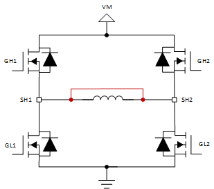 Figure 6. SH1 to SH2 Pin Short
 Table 1 provides a recap on which VDS monitors detect an OCP condition under the different fault scenarios for each operating mode.
Table 1. VDS Monitors Triggered Per Operating Mode
| Operating Modes | ||||
|---|---|---|---|---|
| Fault Type | Coast Hi-Z | Reverse (SH2SH1) | Forward (SH1SH2) | Brake Low-side Slow Decay |
| Short to VM Case 1 | No Detect | GL1 | No Detect | GL1 |
| Short to VM Case 2 | No Detect | No Detect | GL2 | GL2 |
| Short to GND Case 1 | No Detect | No Detect | GH1 | No Detect |
| Short to GND Case 2 | No Detect | GH2 | No Detect | No Detect |
| SH1 to SH2 Pins Short | No Detect | GH2 and GL1 | GH1 and GL2 | No Detect |