SLVAF46A May 2021 – January 2023 TPS65988
2.4 Control Logic Implementation with GPIO Events
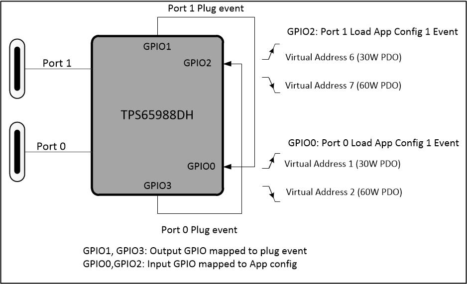
Figure 2-6 shows pictorial representation of Events and GPIOs used in the Dual port power socket design with power balancing.
 Figure 2-6 GPIO Events Usage in Dual Port Power Socket
Design with Power Balancing
Figure 2-6 GPIO Events Usage in Dual Port Power Socket
Design with Power Balancing- Output Plug event GPIOs: GPIO1 (Port-1 plug event) and GPIO3 (Port-0 plug event) are configured to assert on PLUG_EVENT event. These output GPIOs should assert high when a device is connected to the corresponding Port.
- Application Configuration event GPIOs: GPIO2 (Port-1 App Config) and GPIO0 (Port-0 App Config) are input GPIOs configured to load the appropriate configuration (100% or 50% PDOs) based on the input signal and also execute a PD message task (to send SSrC - PD Send Source Capabilities).
The output Plug event GPIOs are connected to the input App Config GPIOs of the alternate port. When the input GPIO of a particular port is high (implies plug event on the other port), input GPIO event shall load 50% Power PDO configuration. Otherwise, when the input GPIO of a particular port is low (implies no PLUG_EVENT on the other port, for example, when the other port in disconnected state), input GPIO event shall load 100% Power PDO configuration. This implementation can be tested on TPS65988D EVM using the project file available on the E2E Design Support forum.