SLVAF59 April 2021 TPS2372 , TPS2373 , TPS23730 , TPS23731 , TPS23734 , TPS2375 , TPS2375-1 , TPS23750 , TPS23751 , TPS23752 , TPS23753A , TPS23754 , TPS23754-1 , TPS23755 , TPS23756 , TPS23757 , TPS23758 , TPS2376 , TPS2376-H , TPS2377 , TPS2377-1 , TPS23770 , TPS2378 , TPS2379
3.4 Feedback Loop
The feedback loop uses the current control mode theory. These contribute to a good bode plot, which ultimately leads to good startup, shutdown, and load transient performance.
If the design is Primary Side Regulation (PSR), please see the above notes in Section 3.2.
Check the linear voltage regulator. High voltage designs >5-V (for example, 12-V) use TL431 parts. Low voltage designs =<5-v use TLV431. The difference is the lower voltage reference, which allows a lower voltage turn on of the feedback system.
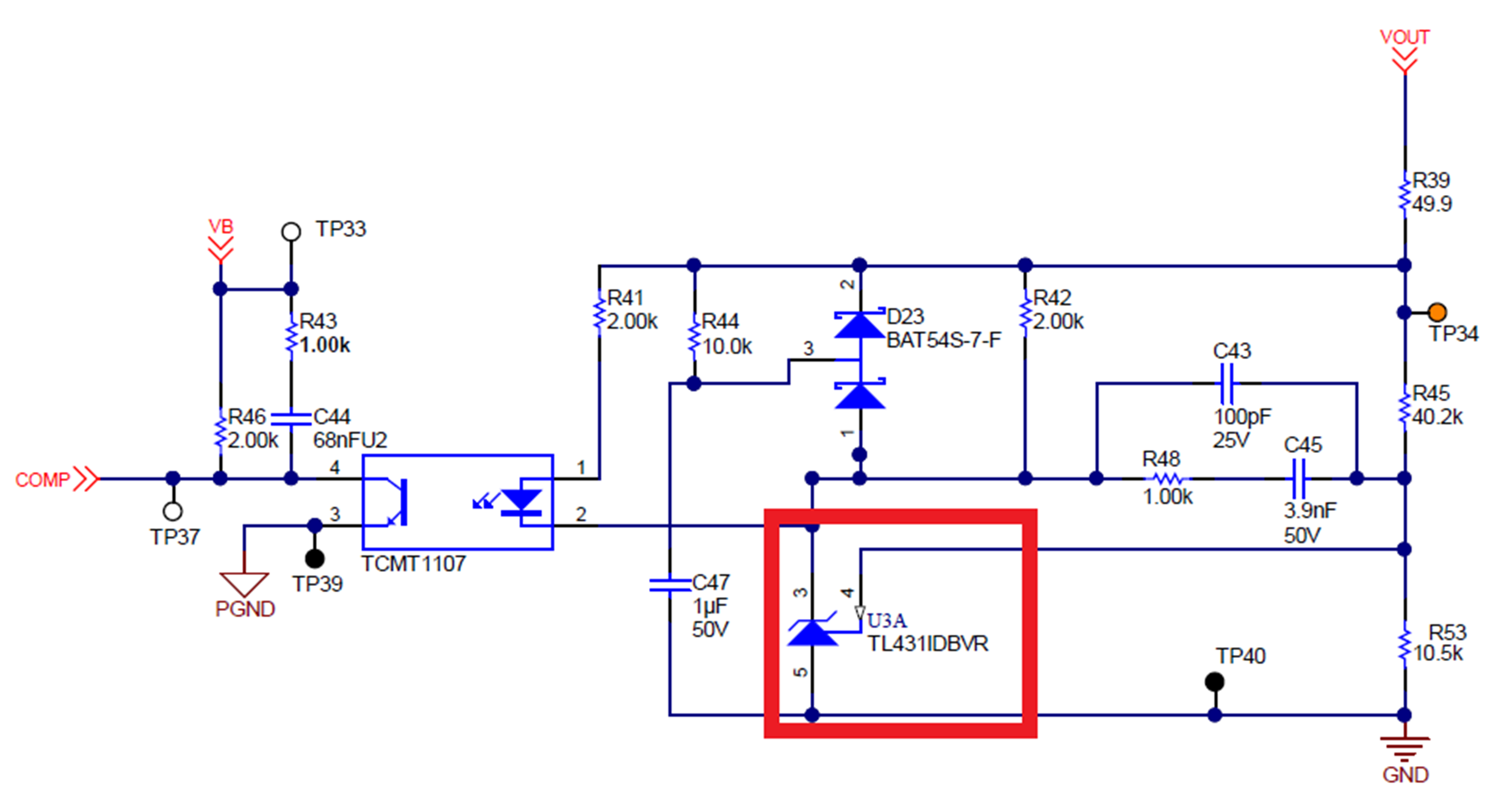 Figure 3-18 Linear Regulator
Check the voltage divider to ensure it gives the proper reference voltage for the linear regulator with the output voltage. If the customer is changing the output voltage (example, from 12-V to 11-V), change the bottom resistor. The top resistor sets many of the poles and zeros, so changing the bottom one introduces less change in the system.
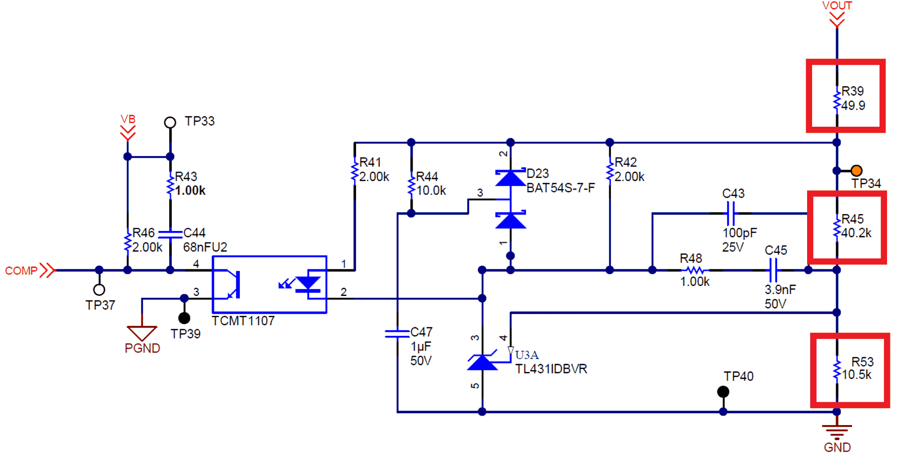 Figure 3-19 Feedback Resistor
Divider
Figure 3-19 Feedback Resistor
DividerCheck that there are protection diodes for these circuits. They provide voltage protection during ESD events. Otherwise there is no protection for these parts. Ensure these are actual protection diodes not just regular zeners – they are there to protect against ESD.
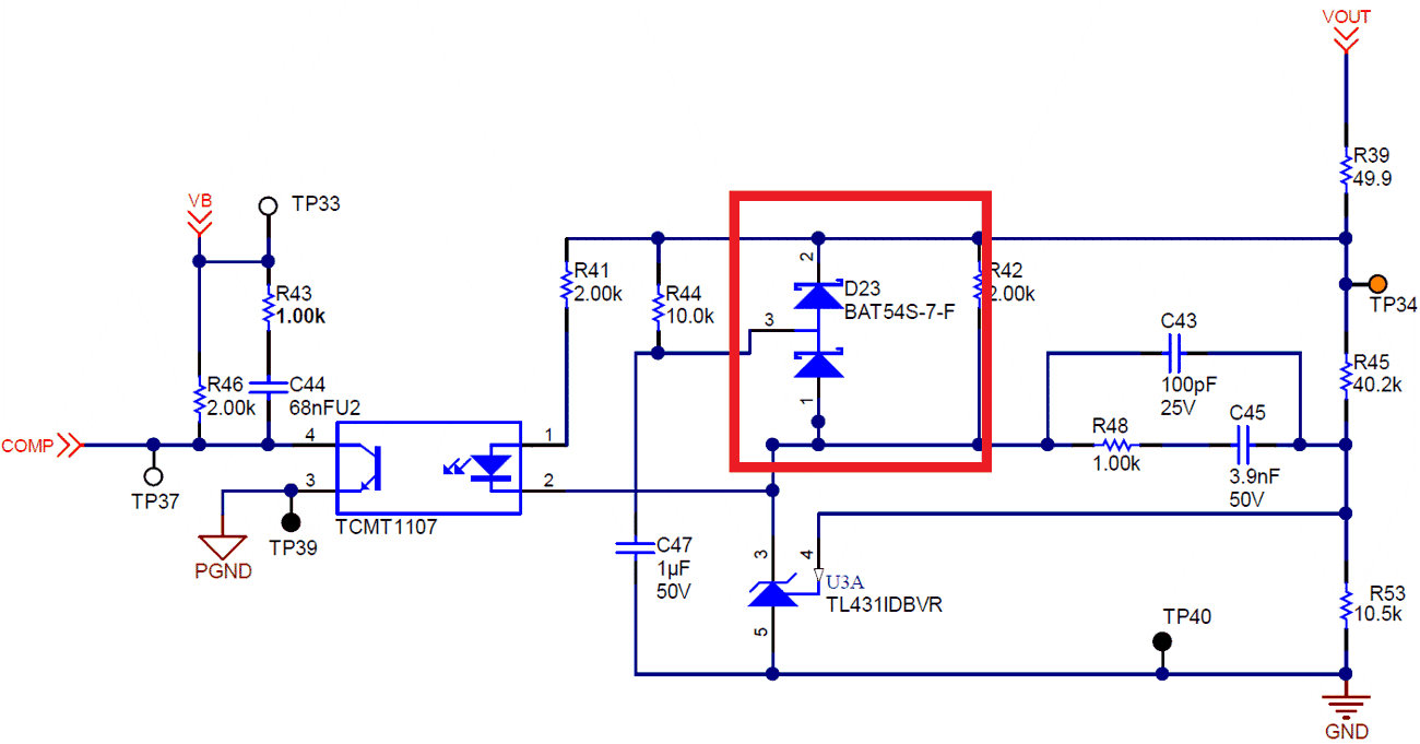 Figure 3-20 Protection Diodes
Check the secondary soft-start circuit. Ensure there is a 10K and 1uF to start. Increasing this cap increases the soft-start time. Having a soft-start here on the secondary is important for overshoot on the output. Without it, the risk of overshoot and the potential damage from that overshoot is increased.
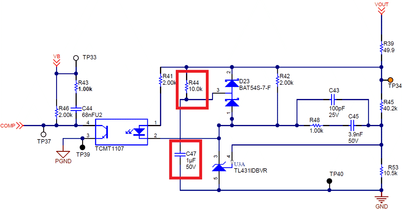 Figure 3-21 Secondary Side Soft
Start
Figure 3-21 Secondary Side Soft
StartCheck the pole and zero caps. It is suggested to compare against a known working design. They can be calculated (also in the above paper), but Fourier transforms are required and typically they need to be adjusted on the board also. It is strongly suggested copying something that works. Calculating feedback components can be tedious.
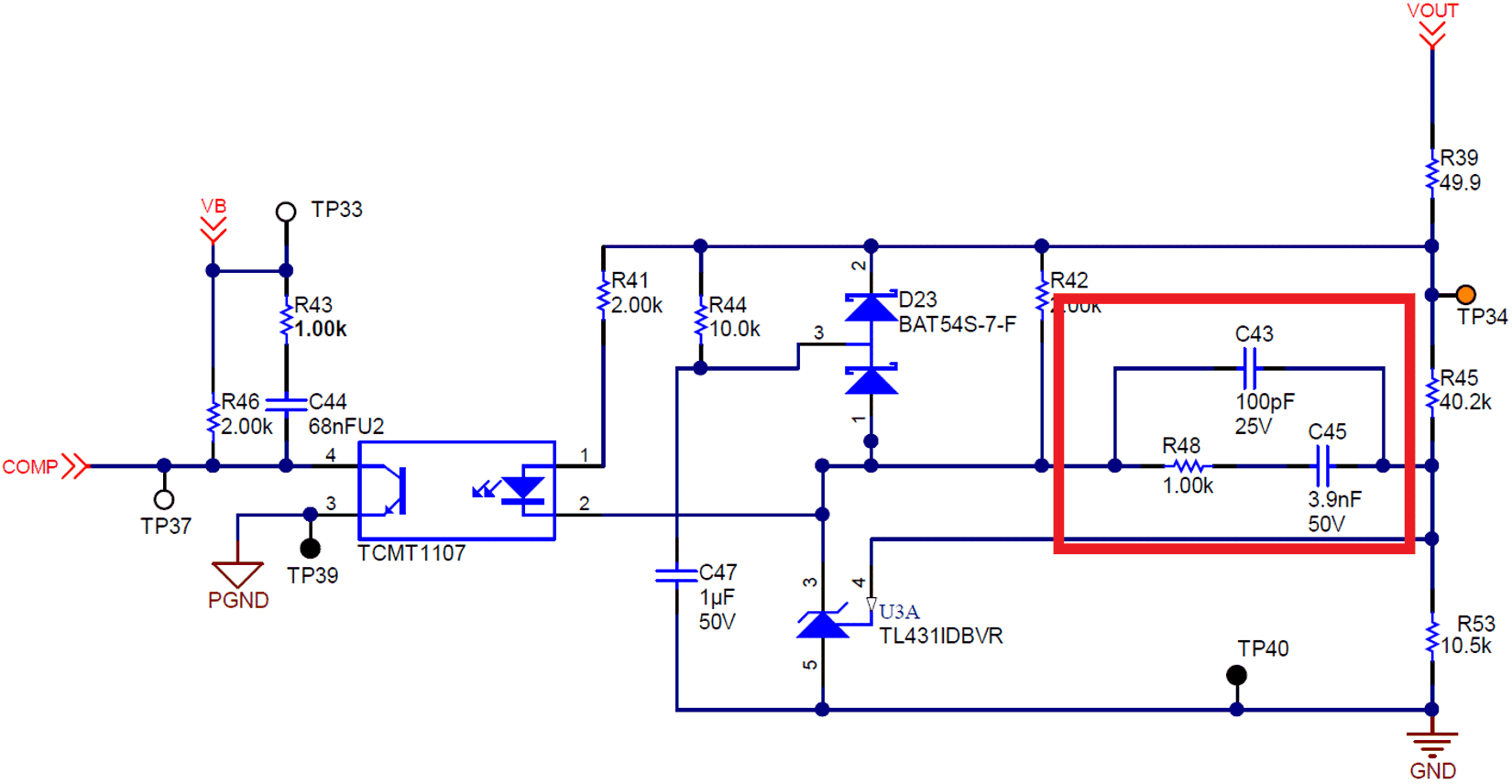 Figure 3-22 Feedback Poles and
Zeros
Figure 3-22 Feedback Poles and
ZerosEnsure the opto-biasing resistor is set properly. This resistor sets the current through the opto, and also sets a gain factor with the resistor on the other side.
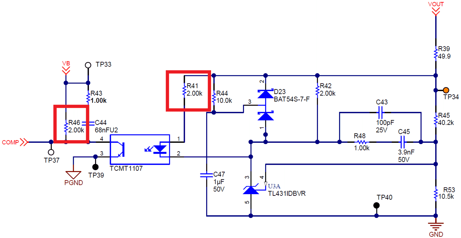 Figure 3-23 Optocoupler Biasing
Resistors
Figure 3-23 Optocoupler Biasing
ResistorsThe Vb poles and zeros also contribute to the feedback loop. Same comments as above for calculations
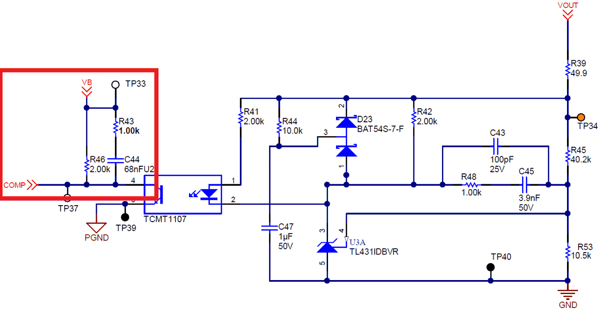 Figure 3-24 Primary Side Poles and
Zeros
Figure 3-24 Primary Side Poles and
Zeros80%-160%. Some optocouplers give the range of 100%-200%, which is also acceptable. All of the feedback is based on this fact. Otherwise, it must be factored into the gain equation, which usually it is not. It is strongly advised keeping it this way. Normally, optocuplers come in part families, with the CTR defined by the last letter (example, -A, -B…-G). Always ensure it is -A. Confirm with the customer that the CTR chosen is 80%-160%. Sometimes the -G part is cheaper because the -G is defined at 80%-600% -- for example, it is untested. If the gain is inconsistent, they will have some boards work and some boards that do not word. This can be a difficult debug process.
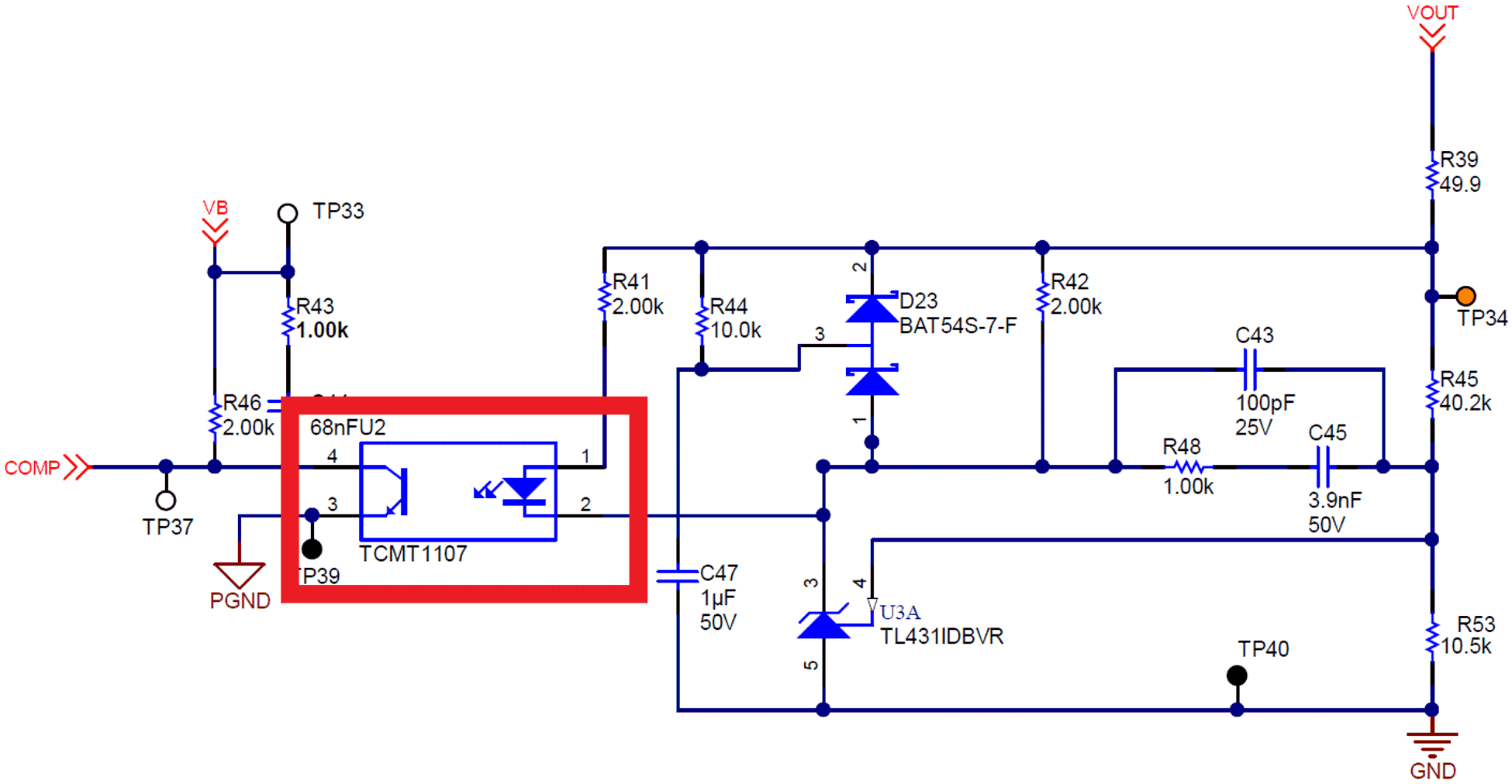 Figure 3-25 Optocoupler