SLVAFJ1 February 2023 TPS2121
2.3 Overvoltage Calculation
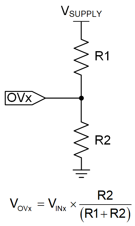
Output overvoltage protection is available for both IN1 and IN2 if either applied voltage is greater than the maximum supported load voltage. The VREF comparator on the OV1 and OV2 pins allows for the overvoltage protection threshold to be adjusted independently. When overvoltage is engaged, the corresponding channel turns off immediately if the pin reaches 1.1 V. Then TPS2121 will utilize the switchover to the other input if it is a valid voltage. However, OVP for IN2 is not used in this design example.
 Figure 2-8 OV Resistors
In this design example, overvoltage on channel 1 is programmed to 7 V which is maximum voltage from IN1. The OV resistor calculations is shown in Equation 4.