SLVU047A February 2001 – March 2022 TPS2330 , TPS2331 , TPS5102
3 Schematics of the EVM and the Interface
To demonstrate a hot-plug or hot-removal application, the evaluation system includes two boards: one is the hot-swappable InfiniBand bulk power EVM (SLVP185 board) where the TPS2331 and TPS5102 reside and control power MOSFETs; the other is an interface card (SLVP155 board) that supplies power and a control signal to the InfiniBand bulk power EVM.
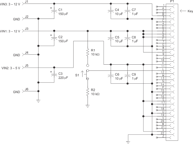
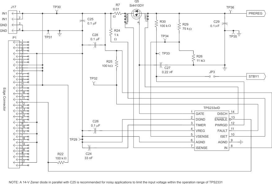
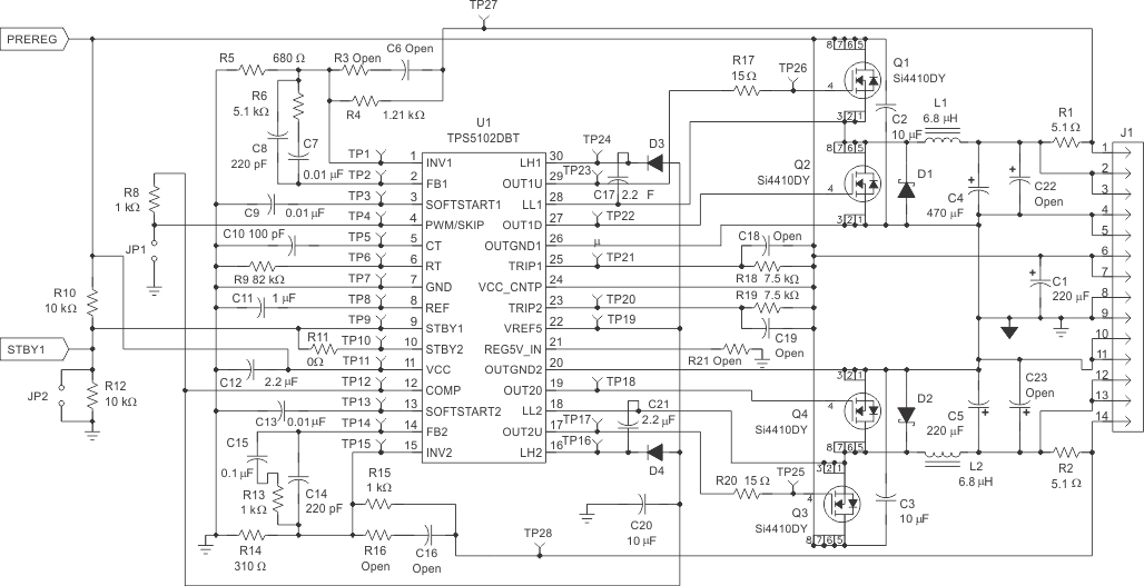
Figure 3-1 and Figure 3-2 show the schematic of the interface card and the schematic of the hot-swappable EVM, respectively.
Since the interface card was originally designed for universal application purposes, some of the components shown in the schematic above may not be on the board when shipped with this EVM kit. Refer to Table 3-1 for a complete components list.
When testing the EVM, set the slide switch S1 on the interface card (SVLP155) to HI (marked on the board), because the hot-swap controller TPS2331 is an active-high enabling device. The user can replace the TPS2331 with TPS2330 in order to evaluate the latter, but will need to switch S1 to LO to perform the evaluation.
 Figure 3-1 Schematic of the Interface
Card (SLVP155)
 Figure 3-2 Schematic of the InfiniBand
Bulk Power Evaluation Module (EVM) Part 1
 Figure 3-3 Schematic of the InfiniBand
Bulk Power Evaluation Module (EVM) Part 2
Figure 3-3 Schematic of the InfiniBand
Bulk Power Evaluation Module (EVM) Part 2The schematic for InfiniBand bulk power EVM (Figure 3-2) shows three jumpers (JP1, JP2, and JP3). JP1 is used to set the DC/DC converter stage in PWM (normal) or skip (power-saving) mode. For normal operation, short JP1, then the converter will be in PWM mode. JP2 is used to shut down the DC/DC converter when it is shorted, so this jumper should not be shorted if the DC/DC conversion is required. JP3 should be shorted for InfiniBand bulk power evaluation because the InfiniBand specification recommends the power-good signal of the hot-swap stage to enable the DC/DC converter.
A 14-V Zener diode in parallel with C25 is recommended if the backplane power is noisy or has potential high voltage spikes, higher than 14 V.
Several components along with the jumpers and test points are only for evaluation purposes and are not necessary for the hot-swap, DC/DC, or both applications. Refer to the data sheets to optimize the designs.
A key is installed in the edge connector on the interface board (SLSP155) to ensure that the board can only be inserted in the correct direction.
The bills of materials (BOM) for both boards are shown in Table 3-1 and Table 3-2, respectively.
| Ref Des | Qty | Part Number | Description | MFG | Size |
|---|---|---|---|---|---|
| C1, C3 | Not used | ||||
| C2 | 1 | LSR100/16DK125 | Capacitor, tantalum, 100 μF, 16 V, 10% | NEMCO | D case |
| C4, C6 | Not used | ||||
| C5 | 1 | GMK325F106ZH | Capacitor, ceramic, 1 μF, 16 V | Taiyo Yuden | 1210 |
| C7, C9 | Not used | ||||
| C8 | 1 | GRM40X7R105K16 | Capacitor, ceramic, 1 μF, 16 V | MuRata | 0805 |
| J3, J4 | 2 | 3267 | Connector, banana jack, uninsulated | Pomona | |
| J1, J2, J5, J6 | Not used | ||||
| P1 | 1 | 40-22SN-11 | Connector, 44-pin edge w/ mtg tabs (for 0.06-inch PCB) | Cinch | |
| R1, R2 | 2 | Std | Resistor, chip, 10 kΩ, 1/10 W, 5% | Std | 1206 |
| S1 | 1 | EG1218 | SW-1C-200 MA-SL | ||
| TP1 | 1 | 240-345 | Test point, red, 1 mm | Farnell | |
| TP5 | 1 | 240-333 | Test point, black, 1 mm | Farnell | |
| TP2-TP4, TP6 | Not used | ||||
| Key | 1 | 50-PK-3 | Key for P1 (Newark #57F3275) | Cinch | |
| 4 | 534-1804 | Spacer, aluminum, 4-40 female, 0.625 inches long | Mouser | ||
| 4 | Screw, pan head Philips, 4-40 × 0.25 inches |
| Ref Des | Qty | Part Number | Description | MFR | Size |
|---|---|---|---|---|---|
| C7, C9, C13 | 3 | GRM40X7R103K25 | Capacitor, ceramic, 0.01 μF, 25 V | MuRata | 805 |
| C25, C26, C28, C29 | 4 | C0805C104K5RAC | Capacitor, ceramic, 0.1 μF, 50 V | Kemet | 805 |
| C15 | 1 | C0805C104K5RAC | Capacitor, ceramic, 0.1 μF, 50 V | Kemet | 805 |
| C27 | 1 | PCCC1832TR–ND | Capacitor, ceramic, 0.22 μF, 25 V | Panasonic | 805 |
| C11 | 1 | GRM40X7R105K16 | Capacitor, ceramic, 1 μF,16 V | MuRata | 805 |
| C24 | 1 | GRM40X7R333K25 | Capacitor, ceramic, 33 nF, 16 V | MuRata | 805 |
| C10 | 1 | GRM40X7R105K16 | Capacitor, ceramic, 100 pF, 16 V | MuRata | 805 |
| C8 | 2 | GRM33X7R221K6 | Capacitor, ceramic, 220 pF, 16 V | MuRata | 805 |
| C14 | GRM33X7R221K6 | Capacitor, ceramic, 220 pF, 16 V | MuRata | 805 | |
| C6, C16, C18, C19 | 4 | OPEN | OPEN | 805 | |
| C12, C17, C21 | 3 | GMK316F225ZG | Capacitor, ceramic, 2.2 μF,35 V | Taiyo Yuden | 1206 |
| C2, C3 | 2 | GMK325F106ZH | Capacitor, ceramic, 10 μF,35 V | Taiyo Yuden | 1210 |
| C20 | 1 | GRM325F106ZH | Capacitor, ceramic, 10 μF,35 V | Taiyo Yuden | 1210 |
| C5 | 1 | 10TPB220M | Capacitor, POSCAP, 220 μF, 4 V | Sanyo | D Case |
| C4 | 1 | 4TPB470M | Capacitor, POSCAP, 470 μF, 4 V | Sanyo | D Case |
| C22, C23 | 2 | OPEN | OPEN | D Case | |
| C1 | 1 | RV–35V221MH10–R | Capacitor, electrolytic, 220 μF, 35 V | ELNA | 10 × 10 mm |
| P1 | 1 | N/A | 44-pin edge | N/A | |
| D1 | 2 | MBRS340T3 | Diode, Schottky, 40 V, 3 A | Motorola | SMC |
| D2 | MBRS340T3 | Diode, Schottky, 40 V, 3 A | Motorola | SMC | |
| D3 | 2 | SD103–AWDICT | Diode, switching, 200 mA, 40 V | Diodes Inc | DL-35 |
| D4 | SD103–AWDICT | Diode, switching, 200 mA, 40 V | Diodes Inc | DL-35 | |
| J17 | 1 | PTC36SAAN | Header, 4-pin, 100-mil spacing (36-pin strip) | Sullins | |
| J1 | 1 | PTC36SAAN | Header, 14-pin, 100-mil spacing (36-pin strip) | Sullins | |
| L1, L2 | 2 | DO3316P-682 | Inductor, SMT 6.8 μH, 4.4 A | Colicraft | |
| JP1, JP2, JP3 | 3 | PTCSAAN | Header, 2-pin, 100-mil spacing (36-pin strip) | Sullins | |
| R11 | 1 | Std | Resistor, chip, 0 Ω, 1/10 W, 5% | Std | 805 |
| R8, R13, R15 | 3 | Std | Resistor, chip, 1 kΩ, 1/10 W, 5% | Std | 0805 |
| R4 | 1 | Std | Resistor, chip, 1.21 kΩ,1/10 W, 1% | Std | 0805 |
| R1, R2 | 2 | Std | Resistor, chip, 5.1 Ω, 1/10 W, 5% | Std | 805 |
| R6 | 1 | Std | Resistor, chip, 5.1 kΩ,1/10 W, 5% | Std | 805 |
| R18, R19 | 2 | Std | Resistor, chip, 7.5 kΩ, 1/10 W, 5% | Std | 805 |
| R10 | 2 | Std | Resistor, chip, 10 kΩ, 1/10 W, 5% | Std | 805 |
| R12 | Std | Resistor, chip, 10 kΩ, 1/10 W, 5% | Std | 805 | |
| R17, R20 | 2 | Std | Resistor, chip, 15 Ω, 1/10 W, 5% | Std | 805 |
| R9 | 1 | Std | Resistor, chip, 82 kΩ, 1/10 W, 5% | Std | 805 |
| R14 | 1 | Std | Resistor, chip, 310 Ω, 1/10 W, 1% | Std | 805 |
| R5 | 1 | Std | Resistor, chip, 680 Ω, 1/10 W, 1% | Std | 805 |
| R3, R16, R21 | 3 | Std | OPEN | 805 | |
| R24 | 1 | Std | Resistor, chip, 1 Ω, 1/8 W, 5% | Std | 1206 |
| R26 | 1 | Std | Resistor, chip, 11 Ω, 1/8 W, 5% | Std | 1206 |
| R29 | 1 | Std | Resistor, chip, 75 Ω, 1/8 W, 5% | Std | 1206 |
| R22, R25, R30 | 3 | Std | Resistor, chip, 100 Ω, 1/8 W, 5% | Std | 1206 |
| R7 | 1 | WSL–2512–01, 1%,R86 | Resistor, chip, 0.01 Ω, 1 W, 1% | Dale | 2512 |
| U2 | 1 | TPS2330ID | Single hot-swap P/controller w/ circuit breaker and PG | TI | SO14 |
| U1 | 1 | TPS5102DBT | IC, dual controller, PWM/skip mode | TI | DBT30 |
| TP7,TP29, TP31, TP35 | 4 | 240–333 | Testpoint, black, 1 mm | Farnell | DBT30 |
| TP1–TP6,TP8–TP28,TP30, TP32, TP33, TP34, TP36 | 32 | 240–345 | Testpoint, red, 1 mm | Farnell | |
| Q1–Q5 | 5 | Si4410DY | MOSFET, N-ch, 30 V, 10 A, 13 mW | Siliconix | SO8 |
| Shuntsfor JP1, JP2 | 2 | 929950-00 | Jumper shunt | 3M |