SLVU775A September 2012 – November 2021 TPS5402
6 Schematic and Bill of Materials
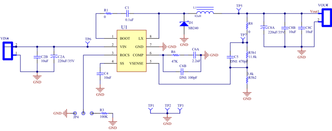
The following pages contain the TPS5402EVM schematic and bill of materials.
 Figure 6-1 TPS5402EVM Schematic
Table 6-1 TPS5402EVM Bill of Materials
| ITEM NO. | QTY | DESIGNATOR | VALUE | MANUFACTURER | PART NO. | DESCRIPTION |
|---|---|---|---|---|---|---|
| 1 | 1 | C1 | 0.1 μF | Generic | Capacitor, 0.1 μF, 35 V, Ceramic, X7R, 0603 | |
| 2 | 3 | C2, C8B, C8C | 10 μF | Generic | Capacitor, 10 μF, 35 V, Ceramic, X5R, 0805 | |
| 3 | 2 | C2A, C8A | 220 μF | Rubycon | 5YXF220MEFC | 220 μF/35 V 10x12.5 |
| 4 | 1 | C4 | 10 nF | Generic | Capacitor, 10 nF, 35 V, Ceramic, X7R, 0603 | |
| 5 | C5 | 470 pF | Generic | Capacitor, 470 pF, 50 V, Ceramic, X7R, 0603 | ||
| 6 | 1 | C6A | 2.2 nF | Generic | Capacitor, 2.2 nF, 50 V, Ceramic, X7R, 0603 | |
| 7 | DNI | C6B | 100 pF | Generic | Capacitor, 100 pF, 50 V, Ceramic, X7R, 0603 | |
| 8 | 1 | D1 | Comchip | SB240E | Comchip SB240E 2-A/40-V Schottky Rectifier | |
| 9 | 1 | JP4 | Mill-Max Manufacturing Corp. | 800-10-064-10-001000 | Three Pin Jumper, SIP HEADER 64 POS STRAIGHT PCB | |
| 10 | 1 | L1 | 82 μH | Bourns | RL622-820K-RC | Magnetic-Core Inductor |
| 11 | 2 | R1, R8 | 0 | Generic | Resistor, 1%, 1/10W, 0603, SMD | |
| 12 | 1 | R3 | 100 K | Generic | Resistor, 1%, 1/10W, 0603, SMD | |
| 13 | 1 | R6 | 30 K | Generic | Resistor, 1%, 1/10W, 0603, SMD | |
| 14 | 1 | R5b1 | 11.8 k | Generic | Resistor, 1%, 1/10W, 0603, SMD | |
| 15 | 1 | R5b2 | 3.8 k | Generic | Resistor, 1%, 1/10W, 0603, SMD | |
| 16 | 2 | TP1, TP2 | 5001 | Generic | 5001 | Keystone Electronics, Test Point, Black |
| 17 | 3 | TP5, TP6, TP7 | 5002 | Generic | 5002 | Keystone Electronics, Test Point, White |
| 18 | 1 | U1 | Texas Instruments | TPS5402 | SOIC8 | |
| 19(1) | 1 | Sullins Connector Solutions | SPC02SYAN | SPC02SYAN, CONN JUMPER SHORTING GOLD FLASH |
(1) Install item 19 on item 8 to the inner side.