SLVU777A September   2012  – November 2021 TPS54020


  1.   Trademarks
  2. 1Introduction
    1. 1.1 Background
    2. 1.2 Performance Specification Summary
    3. 1.3 Modifications
      1. 1.3.1 Output Voltage Setpoint
      2. 1.3.2 Slow-Start Time
      3. 1.3.3 Adjustable UVLO
      4. 1.3.4 Input Voltage Rails
  3. 2Test Setup and Results
    1. 2.1  Input / Output Connections
    2. 2.2  Efficiency
    3. 2.3  Output Voltage Load Regulation
    4. 2.4  Output Voltage Line Regulation
    5. 2.5  Load Transient
    6. 2.6  Control Loop Response
    7. 2.7  Output Voltage Ripple
    8. 2.8  Input Voltage Ripple
    9. 2.9  Start Up
    10. 2.10 Pre-Bias Start Up
    11. 2.11 Hiccup Mode Current Limit
  4. 3Board Layout
    1. 3.1 Layout
  5. 4Schematic and Bill of Materials
    1. 4.1 Schematic
    2. 4.2 Bill of Materials
  6. 5Revision History

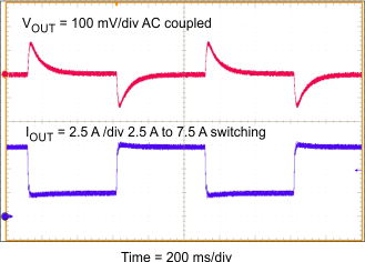
Load Transient

Figure 2-4 shows the EVM response to load transients. The current step is from 0 A to 4.7 A with an input voltage of 5 V. The transient was applied by switching in a real resistor load. The current step slew rate is approximately 50 A/μs. Total peak-to-peak voltage variation is as shown, including ripple and noise on the output.

ParameterDescription
Bottom TraceOutput current switching between 2.5 A and 7.5 A, 2.5 A/div
Top traceOutput voltage, AC coupled, at 100 mV/div
Time Scale200 µs/div
ConditionsInput voltage = 12 V, temperature = 25°C
GUID-06B21165-5207-4C99-923D-DDB8558222ED-low.gifFigure 2-4 TPS54020EVM-082 Transient Response