SLVUAM8B December 2015 – August 2021 TPS54A20
1.4.2 On Time
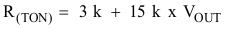
The TON pin requires a resistor to set the nominal on-time and to support the input voltage feed forward circuit. The resistance value used also influences the internal ramp in the controller. Use Equation 2 for selecting the TON resistor.
The RTON resistor selected for this design example is 22.1 kΩ. During startup, the converter uses the nominal on-time programmed through TON. The phase lock loop (PLL) is only activated after startup is complete. When the PLL is engaged, the on-time is adjusted. If the nominal on-time programmed through the TON pin is not close to the on-time when the PLL is engaged, the SYNC range of the device may be reduced. The TON resistor can also be adjusted to tune the controller. Lowering the RTON value will increase the internal ramp height. This will reduce the converter’s sensitivity to noise and jitter but it will also reduce the transient response capabilities of the converter.