SLVUC46D March 2021 – November 2023
2.2.5 Current Limit Header (RIPROPI)
The DRV824x and DRV814x family of devices integrate a current sense output using current mirrors on the low-side power MOSFETs on the IPROPI device pin. The IPROPI pin sources a small current proportional to the current in the high side MOSFETs (current sourced out of the IPROPI pin). The IPROPI current can be converted to a proportional voltage using an external resistor ( RIPROPI). The integrated current sensing allows the DRV824x and DRV814x devices to limit the output current with a fixed off-time PWM chopping scheme and provides load information to an external controller to detect changes in load or stall conditions. The integrated current sensing outperforms traditional external shunt resistor sensing by providing current information even during the off-time slow decay recirculating period. Additionally, BOM cost and PCB area is reduced by eliminating a large external power shunt resistor. The off-time PWM current regulation level can be configured during motor operation through the ITRIP function to limit the load current accordingly to the system demands.
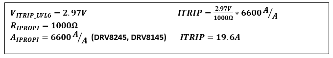
Selecting the RIPROPI value must be done in conjunction with the ITRIP level (configured through SPI or external jumper selection depending on SPI or hardware device variant) and is governed by the following relationship:
Example: (Typical values from DRV8245-Q1 data sheet; AIPROPI vary by part number):
Refer to the Electrical Characteristics CURRENT SENSE AND REGULATION table in device data sheet for RIPROPI values matching the output capability of the device installed on your EVM.
Figure 2-5 shows the header with user selectable RIPROPI values.
 Figure 2-5 RIPROPI
Header
Figure 2-5 RIPROPI
Header