SNLA239C May   2021  – December 2023 DP83867CR , DP83867CS , DP83867E , DP83867IR , DP83867IS , DP83869HM


  1.   1
  2.   Abstract
  3.   Trademarks
  4. 1Standards and System Requirements
    1. 1.1 Standards
    2. 1.2 Test Equipment Suppliers
    3. 1.3 Test System Requirements
    4. 1.4 Software Setup and Installation
  5. 2Ethernet Physical Layer Compliance Testing
    1. 2.1 Standard Test Setup and Procedures
    2. 2.2 1000BASE-T
      1. 2.2.1 Test Mode 1
        1. 2.2.1.1 Template
        2. 2.2.1.2 Peak Voltage
        3. 2.2.1.3 Droop
      2. 2.2.2 Test Mode 2
        1. 2.2.2.1 Jitter Master Unfiltered
      3. 2.2.3 Test Mode 4
        1. 2.2.3.1 Distortion
        2. 2.2.3.2 Common-Mode Voltage
        3. 2.2.3.3 Return Loss
    3. 2.3 100BASE-TX
      1. 2.3.1 Template (Active Output Interface)
      2. 2.3.2 Differential Output Voltage
      3. 2.3.3 Signal Amplitude Symmetry
      4. 2.3.4 Rise and Fall Time
      5. 2.3.5 Waveform Overshoot
      6. 2.3.6 Jitter
      7. 2.3.7 Duty Cycle Distortion
      8. 2.3.8 Return Loss
    4. 2.4 10BASE-Te
      1. 2.4.1 Link Pulse
      2. 2.4.2 10Base-Te Standard
        1. 2.4.2.1 TP_IDL
        2. 2.4.2.2 MAU, Internal
        3. 2.4.2.3 Jitter With TPM
        4. 2.4.2.4 Jitter Without TPM
        5. 2.4.2.5 Differential Voltage
        6. 2.4.2.6 Common-Mode Voltage
        7. 2.4.2.7 Return Loss
        8. 2.4.2.8 Harmonic Content
  6. 3Debug Test Methods
  7. 4References
  8. 5Revision History
  9.   A Outline of Ethernet Compliance Tests for DP8386x
  10.   B Ethernet Compliance Testing MDIO Register Writes for DP8386x

Test Mode 4

Configure PHY to output Test Mode 4 by setting MDIO registers according to 1000 Base Test Mode 4 in Appendix B.
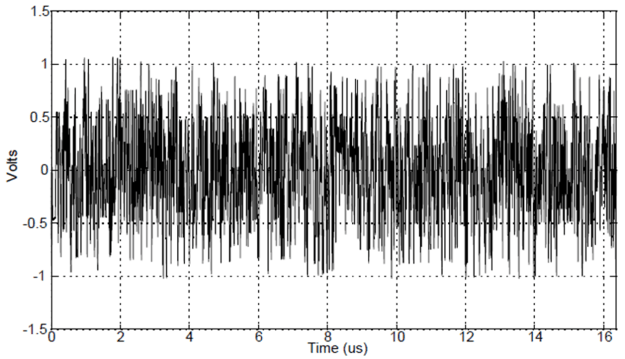
GUID-DC4D3058-D00E-44C9-A7AA-4F4772D0B82A-low.gif Figure 2-6 IEEE Test Mode 4 per Standard
GUID-20231129-SS0I-X9QX-2X30-BMV0QBRPSRC7-low.svg Figure 2-7 DP8386x Test Mode 4 Output Waveform