SNLU262A december 2019 – june 2023 DP83826I
2.2.1 Power Supply
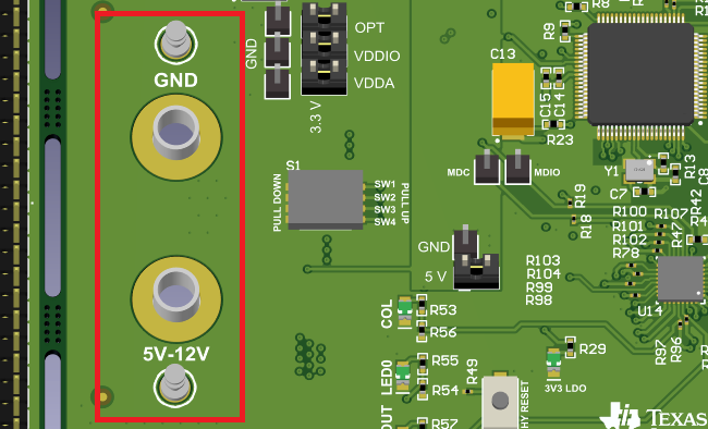
The DP83826EVM power is supplied by the 5-12V input connection in Figure 2-3. Single supply operation uses on-board LDOs to generate the voltages required for operating various sections of the EVM. Power can also be supplied externally to individual voltage rails. The micro-USB supplies power to the on-board LDOs that power all microcontroller related components.
Note:
Before supplying power at the 5-12V input, ensure the correct shunts are added to the appropriate headers to properly operate the on-board LDOs as seen in Figure 2-4.
 Figure 2-3 DP83826EVM Power Headers