SNOAA90A february 2023 – may 2023 DRV5033-Q1 , LDC3114-Q1 , TMAG5170-Q1 , TMAG5170D-Q1 , TMAG5173-Q1
3.3 Encoder Using Hall
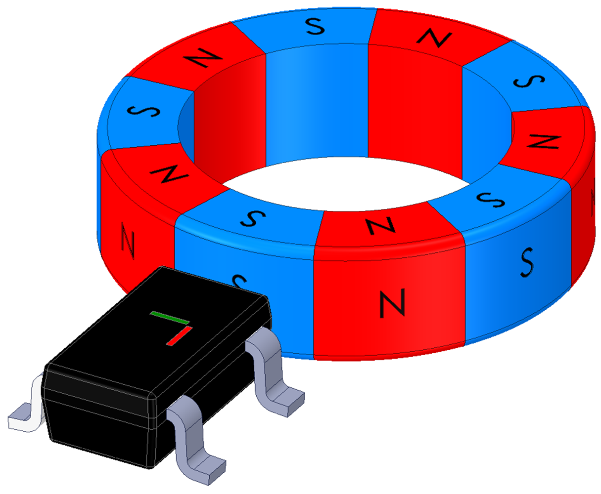
Another Hall implementation for rotational sensing is as an encoder. This method looks at the change in rotation using a transitioning magnetic field polarity over a Hall sensor, typically a Hall-effect latch. These are similar to mechanical rotary encoders in function but remove the electro-mechanical contacts that cause wear and tear. A common way to implement this is to have a ring magnet with multiple poles in the encoder. As the poles move and the magnetic field switches from north to south or vice versa above the magnetic sensor, the output of the switch or latch can be used to show the change in rotational motion. Switches give an output for both polarities of a magnetic field while latches change output state when the magnetic field polarity changes. The TMAG5110 is a 2D latch that gives separate outputs for the X and Y components of the magnetic field. This process provides a quadrature output of the magnet rotation that can give the direction of rotation and an increased number of output states compared to a single 1D latch.
 Figure 3-2 In-Plane Sensor
 Figure 3-3 Magnetic Field
Components
 Figure 3-4 TMAG5110 Output
Alternatively, designers can use multiple 1D latches in a Hall-effect encoder to achieve a similar result. Positioning two latches out of phase gives four unique output conditions as each complete magnetic pole pair pass the sensors.
 Figure 3-5 Dual Latch Placement and Output
The positions of the Hall sensor and the magnet choice of the design are important to achieve a robust output with the desired number of increments per turn. As previously mentioned, devices like the TMAG5110 and TMAG5111 offer a 2D dual output option to give similar results in only one device package. For more information on implementing a quadrature Hall-effect incremental encoder, see the Reducing Quadrature Error for Incremental Rotary Encoding Using 2D Hall-Effect , application note. Hall-effect sensors make encoders easy to design and easy to scale the number of positions per rotation because the design only requires a ring magnet with the correct number of pole pairs for the design to work. However, similar to Hall switches, this implementation can be subject to interference from external DC magnetic fields.