SNWA014 November 2023 LMH2110
3.2 Log Conformance
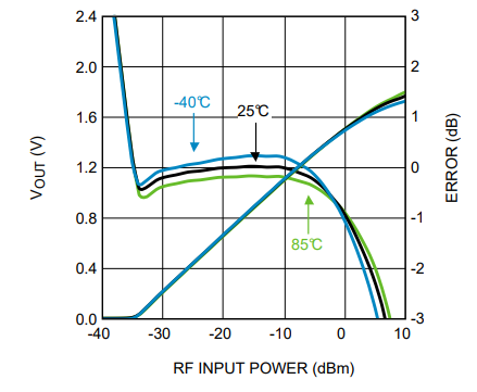
To describe how close the transfer is to a logarithmic function, the log conformance error is used. To calculate the log conformance error the detector transfer function is modeled as a linear-in-dB relationship between the input power and the output voltage. Section 8.2.1.2.1.2 of the LMH2110 8-GHz Logarithmic RMS Power Detector with 45-dB Dynamic Range data sheet explains how the log conformance error is calculated.
 Figure 3-2 VOUT and Log Conformance Error of LMH2110 Across Dynamic Range at 1900 MHz