SPRAD72 February 2023 TMS320F28388D , TMS320F28388S , TMS320F28P650DH , TMS320F28P650DK , TMS320F28P650SH , TMS320F28P650SK , TMS320F28P659DH-Q1 , TMS320F28P659DK-Q1 , TMS320F28P659SH-Q1
2 PHY Selection and Configuration for EtherCAT
When selecting the proper PHY for EtherCAT, first review the Application note – PHY selection guide on the EtherCAT home page. This application note describes the specifications and the recommendations of PHY performance from the EtherCAT perspective. The document also lists a variety of PHYs from TI, such as the DP836x, DP838x, TLK10x, and TLK11x.
Proper configuration of PHY to comply with IEEE 802.3 100BaseTX or 100BaseFX, includes:
- Support 100Mbps full-duplex links
- Provide an MII (or RMII, RGMII) interface
- Auto-negotiation in 100Base TX mode
- Support MII management interface
- MDI, MDI-X auto-crossover in 100BaseTX mode
- Receive and transmit delays must comply with the standard (the RX delay target is below about 320 ns, the TX delay is below about 140 ns)
- Must offer the RX_ER signal (MII, RMII) or RX_ER as part of the RX_CTL signal (RGMII)
- Link loss reaction time (link loss to link signal or LED output change) must be faster than 15 µs to enable redundancy operation
To setup the PHY in the correct mode to work in the EtherCAT environment, the serial management interface (SMI) can be used to program the PHY to be setup in a specific mode.
Up to 32 PHYs can share a common SMI bus. To distinguish between the PHYs, an x-bit address is used. During power up or hardware reset, the PHY device latches the PHY_AD[x:0] configuration pins to determine the address. The address can be changed by adding the required pullup or pulldown resistors defined in the bootstrap section of the PHY device data sheet. The bootstrap pin can also be used for PHY configuration. This application note only focuses on using the SMI. See #GUID-27DBB9E2-FB45-4939-A0E3-826F03E4C20E for the hardware bootstrap diagram.
The C2000 ESC addresses the Ethernet PHYs typically using the logical port number plus the PHY address offset. In the best situation, the Ethernet PHY addresses correspond with the logical port number, so PHY addresses 0 and 1 are used. A PHY address offset of 0 to 31 can be applied which moves the PHY addresses to any consecutive address range. The ESC module expects logical port 0 to have PHY address 0 plus the PHY address offset. The PHY address offset can be selected in register ESCSS_MISC_CONFIG.PHY_ADDR[4:0].
Before entering into the desired operation mode, the PHY device must get out of the RESET condition by applying a high level to the RESET pin. This RESET signal is generated out of the ESC module. Since there are no pull devices active on the MCU during and after reset, a pulldown resistor must be added on this signal on the board level. In some cases, PHYs can be released from reset after releasing the ESC module. To generate a delay, the pin for nPHY_RESET can be used as an I/O and is switched later to the alternate output function. Moreover, a hardware reset can reinitialize all the PHY registers to default values by applying a low pulse, with a duration of at least 10 μs (T1) to the RESET pin (take DP83822 PHY for example, see #GUID-84B7F4FA-0AA0-418D-90DE-9F29ED8BE5C3).
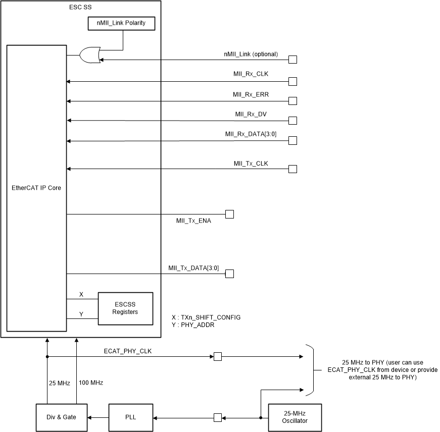
The interface diagram between ESC and PHY device is shown in #GUID-3E254514-88D8-4C00-BC6A-F7003CED3FD2. The PHY can be clocked using the ESCSS_PHY_CLK signal, if needed, otherwise provide an external 25-MHz source to the PHY and ESC (both must be clocked from the same source).
 Figure 2-3 ESC PHY MII Interface
Diagram