SPRUIC4D January 2017 – June 2022
4.3 Evaluation of the Programmable Gain Amplifier (PGA)
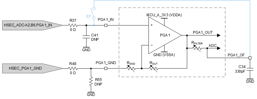
When evaluating the PGA, the PGA_GND pin must be driven to the ground reference of the PGA_IN signal. The PGA_GND signal may be provided using differential signaling through the HSEC fingers for improved noise immunity, or the PGA_GND pin may be tied to the GND reference of the controlCARD through a 0-Ω resistor (R55 in Figure 4-2) for simplicity.
 Figure 4-2 PGA With S7 Open (Output Filter Usable)
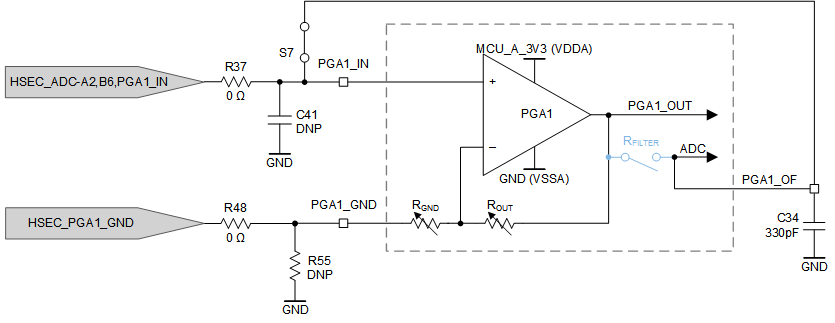
The S7 switch bank provides the flexibility to either use the PGA output filter pin (PGAn_OF) for filtering (S7 open in Figure 4-2) or for sampling the PGA input voltage directly by bypassing the internal PGA (S7 closed in Figure 4-3).
 Figure 4-3 PGA With S7 Closed (Output Filter Not Usable)
The S7 closed implementation for PGA6 is different from the other PGAs. Instead of shorting PGA6_OF and PGA6_IN, the PGA6_OF signal may be accessed from the HSEC connector independently of the PGA6_IN signal.
The PGA RFILTER resistor should never be enabled while the S7 switch is closed. Prolonged exposure to contention between the PGA_IN and PGA_OF pins may result in permanent damage to the internal RFILTER resistor.