SPRUIR8B april 2020 – july 2023
- 1
- CLB Tool
- Trademarks
- 1Introduction
- 2Getting Started
- 3Using the CLB Tool
-
4Examples
- 4.1
Foundational Examples
- 4.1.1 CLB Empty Project
- 4.1.2 Example 3 – PWM Generation
- 4.1.3 Example 7 – State Machine
- 4.1.4 Example 13 – PUSH-PULL Interface
- 4.1.5 Example 14 – Multi-Tile
- 4.1.6 Example 15 – Tile to Tile Delay
- 4.1.7 Example 16 - Glue Logic
- 4.1.8 Exampe 18 - AOC
- 4.1.9 Example 19 - AOC Release Control
- 4.1.10 Example 20 - CLB XBARs
- 4.2
Getting Started Examples
- 4.2.1 Example 1 – Combinatorial Logic
- 4.2.2 Example 2 – GPIO Input Filter
- 4.2.3 Example 4 – PWM Protection
- 4.2.4 Example 5 – Event Window
- 4.2.5 Example 6 – Signal Generation and Check
- 4.2.6 Example 8 – External AND Gate
- 4.2.7 Example 9 – Timer
- 4.2.8 Example 10 – Timer With Two States
- 4.2.9 Example 11 – Interrupt Tag
- 4.2.10 Example 12 – Output Intersect
- 4.2.11 Example 17 – One-Shot PWM Generation
- 4.2.12 Example 21 - Clock Prescaler and NMI
- 4.2.13 Example 22 - Serializer
- 4.2.14 Example 23 - LFSR
- 4.2.15 Example 24 - Lock Output Mask
- 4.2.16 Example 25 - Input Pipeline Mode
- 4.2.17 Example 26 - Clocking Pipeline Mode
- 4.3 Expert Examples
- 4.1
Foundational Examples
- 5Enabling CLB Tool in Existing DriverLib Projects
- 6Frequently Asked Questions (FAQs)
- 7Revision History
3.5.2 Creating the Input Stimulus
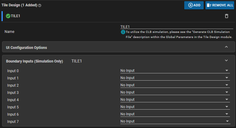
Open the .syscfg file by double-clicking on the file name in the CCS Project Explorer Window. Expand the “Boundary” category by selecting it.
 Figure 3-16 Boundary Input 0 to 7
A separate input stimulus can be defined for each of the eight CLB inputs using the drop-down menus. Click on the down-arrow on the right to reveal the options:
- No Input – Default option, no stimulus is generated.
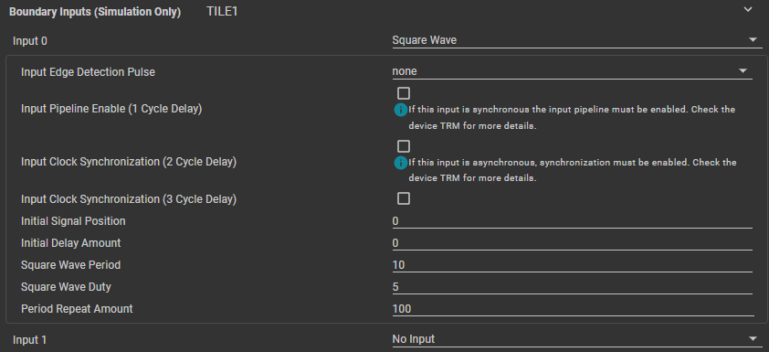
- Square Wave – Defines a periodic PWM input with configurable initial
signal position, initial delay, period, duty, and period repeat amount.
 Figure 3-17 Boundary Input Square Wave
The “Input Edge Detection Pulse” option offers the user the choice of generating a pulse from the rising and/or falling edges of the PWM wave whose period and duty are set as 10 and 5 CLB clock pulses, respectively, in Figure 3-17.
The "Input Pipeline Enable" check-box adds a single cycle delay to the input signal, which is used for synchronized signals which are routed to the CLB as inputs. Note that the pipeline filter is only available on certain CLB types. Check the CLB input mux section in the device-specific TRM for more details.
The “Input Clock Synchronization” check-box forces the input waveform to be synchronized to the CLB clock (the synchronizer creates a 2-3 cycle delay, so there appropriate check-boxes for both timings since the exact delay cannot be predicted). This option is necessary for signals which are coming from asynchronous sources relative to the CLB. For more information, see the CLB input mux section in the device-specific TRM.
- Low (0) or High (1) - Sets the stimulus to a constant low or high, respectively
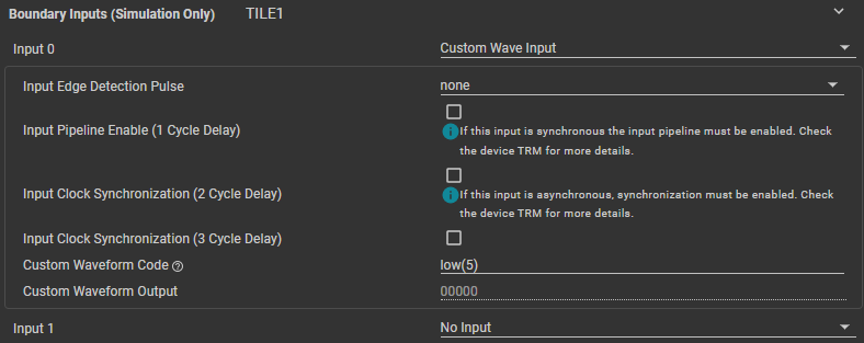
- Custom Wave Input – Generates a custom stimulus using pseduo-code.
 Figure 3-18 Boundary Input Custom
The “Input Edge Detection Pulse”, "Input Pipeline Enable", and “Input Clock Synchronization” work the same as the Square Wave stimulus, with the addition of the custom waveform pseudo-code. The numeric parameter for the 'high', 'low', and 'rpt' instructions can be hexadecimal (0x1A) or decimal (26).
Table 3-2 Custom Waveform Code InstructionsInstruction Description #define Pattern replacer used to define macros high(N) Sets waveform high for 'N' CLB cylces low(N) Sets waveform low for 'N' CLB cycles rpt(N) Starts a repeat block; code encapsulated with rpt(N) and rpt_end will be repeated a total of 'N' times rpt_end Denotes the end of a repeat block - Tile Output -
Uses a selected tile output as the input stimulus for the current tile.
 Figure 3-19 Boundary Input Tile Output
 - "Tile Name" must be the name of a valid tile within the CLB Tool project. The "Input Pipeline Enable" should be enabled since the output of a CLB tile is synchronous. See the CLB input mux section in the device-specific TRM for more information.