SPRUJ22A November 2021 – March 2023 AWR2944
- Trademarks
- 1Getting Started
-
2Hardware
- 2.1 Block Diagram
- 2.2 PCB Handling Recommendations
- 2.3 Power Connections
- 2.4
Connectors
- 2.4.1 MIPI 60-Pin Connector (J19)
- 2.4.2 Debug Connector-60 pin (J7)
- 2.4.3 CAN-A Interface Connector (J3)
- 2.4.4 CAN-B Interface Connector (J2)
- 2.4.5 Ethernet Ports (J4 and J9)
- 2.4.6 USB Connectors (J8, J10)
- 2.4.7 OSC_CLKOUT Connector (J14)
- 2.4.8 PMIC SPI Connector (J16) (DNP)
- 2.4.9 Voltage Rails Ripple Measurement Connectors (J1, J5) (DNP)
- 2.5 Antenna
- 2.6 PMIC
- 2.7 On-Board Sensors
- 2.8 PC Connection
- 2.9 Connecting the AWR2944EVM to the DCA1000 EVM
- 2.10 Jumpers, Switches, and LEDs
- 3Design Files and Software Tools
- 4Revision History
2.10.4 Push Buttons
Table 2-15 Push Button Switches
| Reference | Usage | Comments | Image |
|---|---|---|---|
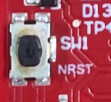
| SW1 | RESET |
This Switch is used to RESET the AWR2944, PMIC, XDS110 and FTDI device. |
 |
| SW2 | GPIO_28 | When pushed, the GPIO_28 shall be pulled to High. | 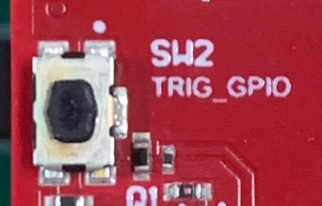 |
| SW3 | CANB_WAKE | Used to Wake up the CANB Transceiver | 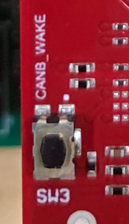 |