SSZT331 february 2020 BQ769142 , BQ76942 , BQ76952 , BQ76972
As we reviewed in my article, Next-generation battery monitors: how to improve battery safety while improving accuracy and extending runtime, accurate monitoring of battery voltage, current and temperature can help ensure safe operation of systems for popular consumer products, including vacuum cleaners, power tools and e-bikes. In this article, we will take a deeper look at temperature monitoring for lithium-based batteries, including proper configuration for safe system operation.
When a lithium-based battery operates outside of the cell manufacturer’s specified temperature range, there is a risk of thermal runaway occurring, which can ultimately result in fire or explosion. Therefore, to ensure the safety of the system and comply with various standards requirements, the battery must be disabled whenever the cell temperature is outside this specified temperature range. But knowing when to disable the battery depends on the accuracy of the battery monitor and protector’s temperature measurement subsystem, making it critical for safe system operation.
The newest additions to TI’s family of battery monitors and protectors, the BQ76942 (3 cells in series [3S], up to 10S) and BQ76952 (3S up to 16S), integrate a 16-/24-bit delta-sigma analog-to-digital converter (ADC), which is multiplexed among various voltage measurements, including measurement of the internal die temperature and external thermistors.
The BQ76942 (10S) and BQ76952 (16S) include an internal die temperature measurement based on the ADC measurement of a ΔVBE voltage using its internal reference. This voltage is converted to a temperature reading, which can be read through the serial communications interface.
Both battery monitors support temperature measurements using external thermistors on up to nine device pins, which provide flexibility for system designers regarding where to measure temperature within the battery pack. It is possible to designate individual thermistor measurements and the internal die temperature reading for use as a cell temperature, field-effect transistor (FET) temperature or neither.
The protection subsystem uses measurements designated as cell temperature to recognize cell over/undertemperature in charge or over/undertemperature in discharge, as well as to determine whether cell balancing is allowed or not. Thermistors designated for FET temperature are used to recognize FET overtemperature. Any thermistors enabled but not designated for cell or FET temperature will be used for temperature reporting, but not used by the protection subsystem.
The internal die temperature also determines whether cell balancing is allowed or not, and whether the device should be put into a shutdown state to avoid erroneous operation beyond its specified operating temperature range.
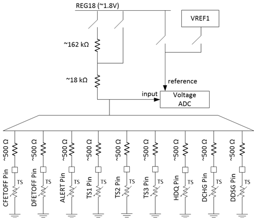
The thermistors are measured while connected to an internal pullup resistor connected to the REG18 (~1.8 V) low-dropout regulator, as shown in Figure 1.
 Figure 1 Temperature Measurement Using
External Thermistors
Figure 1 Temperature Measurement Using
External ThermistorsDuring operation, the device autonomously biases each thermistor one at a time, using an internal pullup resistor programmable to 18 kΩ or 180 kΩ. The pullup resistors are measured during factory trim, with their value stored digitally within the device for use in temperature calculation.
The voltage ADC measures the thermistor pin voltage ratiometrically by using the REG18 voltage as its reference. The voltage on each thermistor is measured every one to three measurement loops, with the raw ADC count value available through the DASTATUS6() subcommand. The device converts these measurements into temperature every 250 ms while in normal mode, or at each measurement interval while in sleep mode.
The BQ76942 and BQ76952 use a fifth-order polynomial to calculate temperature based on the ADC measurement. The devices include default polynomial coefficients for:
- The Semitec 103-AT thermistor (10 kΩ at 25°C, B25/85 = 3,435 k) using the 18-kΩ pullup resistor.
- The Semitec 204AP-2 thermistor (200 kΩ at 25°C, B25/85 = 4,470 k) using the 180-kΩ pullup resistor.
Custom coefficients optimized for use with a different thermistor can also be written into registers or one-time programmable memory.
The temperature calculated for each enabled thermistor is available in units of 0.1°K for readout using the serial communications interface.
Conclusion
The BQ76942 and BQ76952 battery monitors and protectors include a high-performance measurement subsystem that integrates an internal die temperature measurement and supports up to nine external thermistors for cell or FET temperature measurement. These devices can be used in a variety of applications, such as power tools and e-bikes, to ensure system safety by monitoring cell temperature and disabling the battery pack when conditions become dangerous.
Additional Resources
- Read the technical article, “Next-generation battery monitors: how to improve battery safety while improving accuracy and extending runtime.”
- Read the application note, “Easy configuration of BQ76942/52 battery monitors.”