SSZT415 september 2019 TPS7A78
Knowing the difference between a capacitor’s rated value and its actual capacitance is key to ensuring a reliable design. This is especially true when considering high-voltage capacitors used in capacitive drop power supplies for equipment like electricity meters, since losing too much actual capacitance may result in insufficient power to support the application.
With a capacitive drop power supply, the high-voltage capacitor is typically the largest (and one of the more expensive) components in the circuit. When sizing capacitors, it is essential that the actual capacitance can support the load current that the design requires.
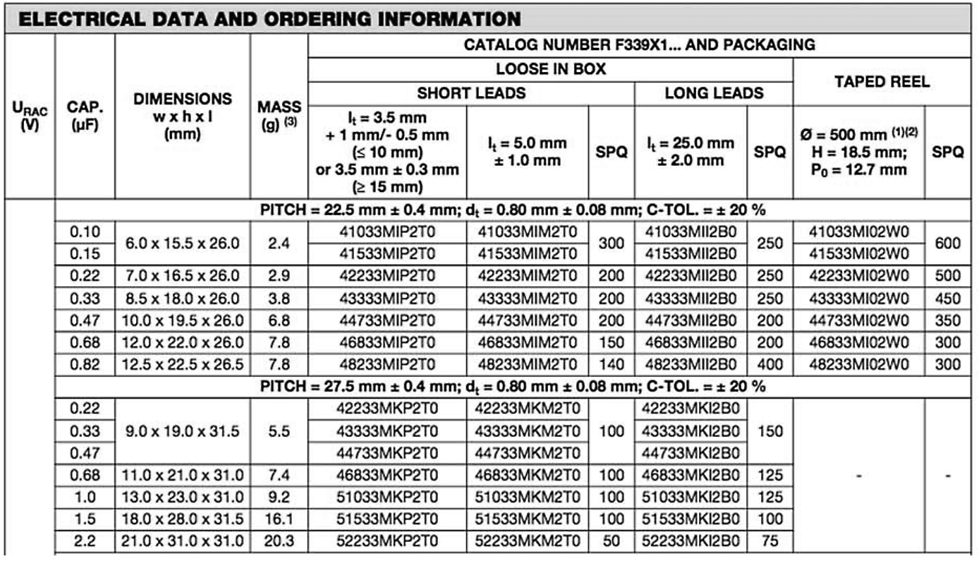
Figure 1 shows the existing capacitance values of capacitors available from a capacitor manufacturer, Vishay. Let’s assume that your design calculations show that your design requires a 1-µF capacitor (90 VAC_RMS at 60 Hz and 5 VOUT @ 25 mA). Considering the available capacitors, you might choose a 1.2-µF capacitor to accommodate the manufacturer’s tolerance of 20%. However, taking into consideration the capacitor’s tolerance and aging effects, you may see a 50% reduction in the actual capacitance of your capacitor over time. In other words, in the worst-case scenario, the 1.2-µF capacitor you chose may only have 0.6 µF of capacitance at its end of life.
 Figure 1 Sample range of high-voltage
capacitors available from manufacturer Vishay
Figure 1 Sample range of high-voltage
capacitors available from manufacturer VishayWait, aging is an issue? If the application is expected to work for 10-plus years, it is not unreasonable to assume that film capacitors may lose ~25% of their capacitance over the lifetime of the product, due to operating temperature, load current and humidity. Table 1 shows a prediction of the total capacitance after considering worst-case tolerance and aging.
| Capacitor
(µF) |
Worst-Case Initial Capacitance (µF) | 10-Year
Aging (µF) |
|---|---|---|
| 0.1 | 0.8 | 0.06 |
| 0.15 | 0.12 | 0.09 |
| 0.22 | 0.176 | 0.132 |
| 0.33 | 0.264 | 0.198 |
| 0.47 | 0.376 | 0.282 |
| 0.68 | 0.544 | 0.408 |
| 0.82 | 0.656 | 0.492 |
| 1 | 0.8 | 0.6 |
| 1.5 | 1.2 | 0.9 |
| 2.2 | 1.76 | 1.32 |
Considering the effects of the tolerances, the best choice to support a 25-mA load at 5 VOUT in a traditional capacitive-drop architecture is a 2.2-µF capacitor, but comes with serious size implications. Is there a better way?
One way to mitigate the effects of capacitance loss due to aging is to simply use a lower-value capacitor. For example, if you used a step-down converter to reduce a DC-rectified 20 V down to 5 V, with perfect efficiency you could maintain 25 mA at the 5-V output, but you would only need to size the high-voltage capacitor to support 6.25 mA. To clarify – in the above example, if a linear power solution required 1 µF, a four-time reduction in voltage will yield a four-time increase in load current capability. In this example, 1 µF reduces to 0.25 µF.
Looking at the same derating for tolerance, you would calculate the need for a 0.3-µF capacitor, yet the next available capacitor has a value is 0.33 µF. Add to that the aging effects, and the next available capacitor you should consider is actually 0.47 µF.
The only problem with a DC/DC step-down converter in applications like electricity meters is that they tend to require a very high level of tamper immunity. Preventing external magnetic fields from impacting the design’s additional circuitry requires Hall-Effect sensors or a tamper-proof enclosure, which adds additional cost.
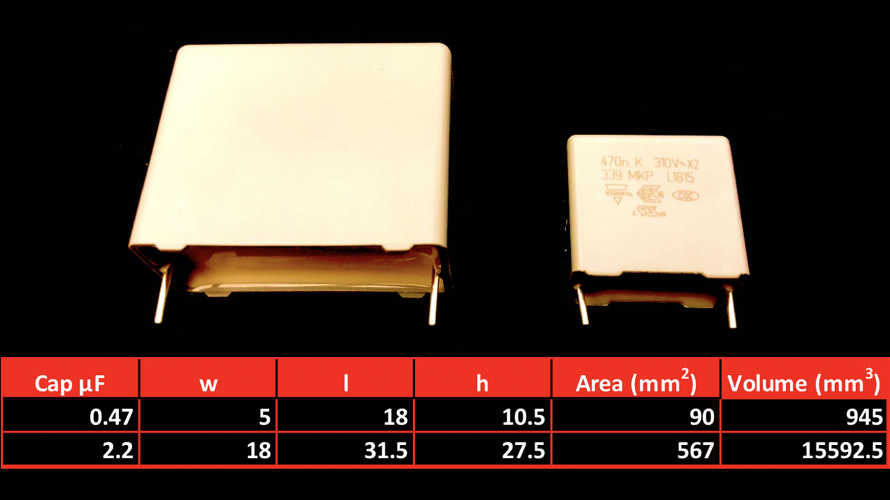
One way to resolve the issue of the oversized capacitor and still support tamper immunity is to use a nonmagnetic step-down converter. TI’s TPS7A78 voltage regulator requires no transformers or inductors to produce a nonisolated low-voltage output. The TPS7A78 reduces a 2.2-µF capacitor to 0.470 mF, guaranteeing 25 mA of load current over the life of the product. Figure 2 compares the area and volume of the two capacitors.
 Figure 2 Area and volume comparison of
two high-voltage capacitors
Figure 2 Area and volume comparison of
two high-voltage capacitorsSo why do smaller capacitors matter? The obvious answer is the overall solution size. But the less obvious benefits are standby power and efficiency. Reducing the amount of capacitance required by four times reduces standby power from ~300 mW down to ~77 mW. Adding the intelligent clamp circuit behind the TPS7A78 supporting a 25-mA load cuts down the total standby power to ~15 mW.
Knowing how to minimize the capacitor to ensure enough capacitance saves cost for both the manufacturer and the consumer when using capacitive drop power supplies.
Additional resources
- To learn more about LDOs, check out the e-book, LDO Basics.
- See how to use a switcher in the application report, Cap Drop Offline Supply for E-Meters.