SSZT596 november 2018 TPS2372 , TPS2373
As the number of interconnected devices in the electronics market continues to grow, it becomes increasingly important to ensure interconnectivity between data-sensitive end equipment like wireless access points (WAPs), Internet Protocol (IP) cameras and security systems. Otherwise, data loss could occur, resulting in the loss of valuable information such as surveillance data. For data-sensitive applications like these, TI is here to help guide you on how to minimize the risk of data loss for Power over Ethernet (PoE) applications.
One method of decreasing the probability of data loss in a PoE system is to implement hitless failover, which enables the transition from main power to backup power without a loss of power at the load (in other words, the load does not reboot/restart and continues in normal operation). Hitless failover helps ensure continuity of service, lowering the probability of power loss and data outages.
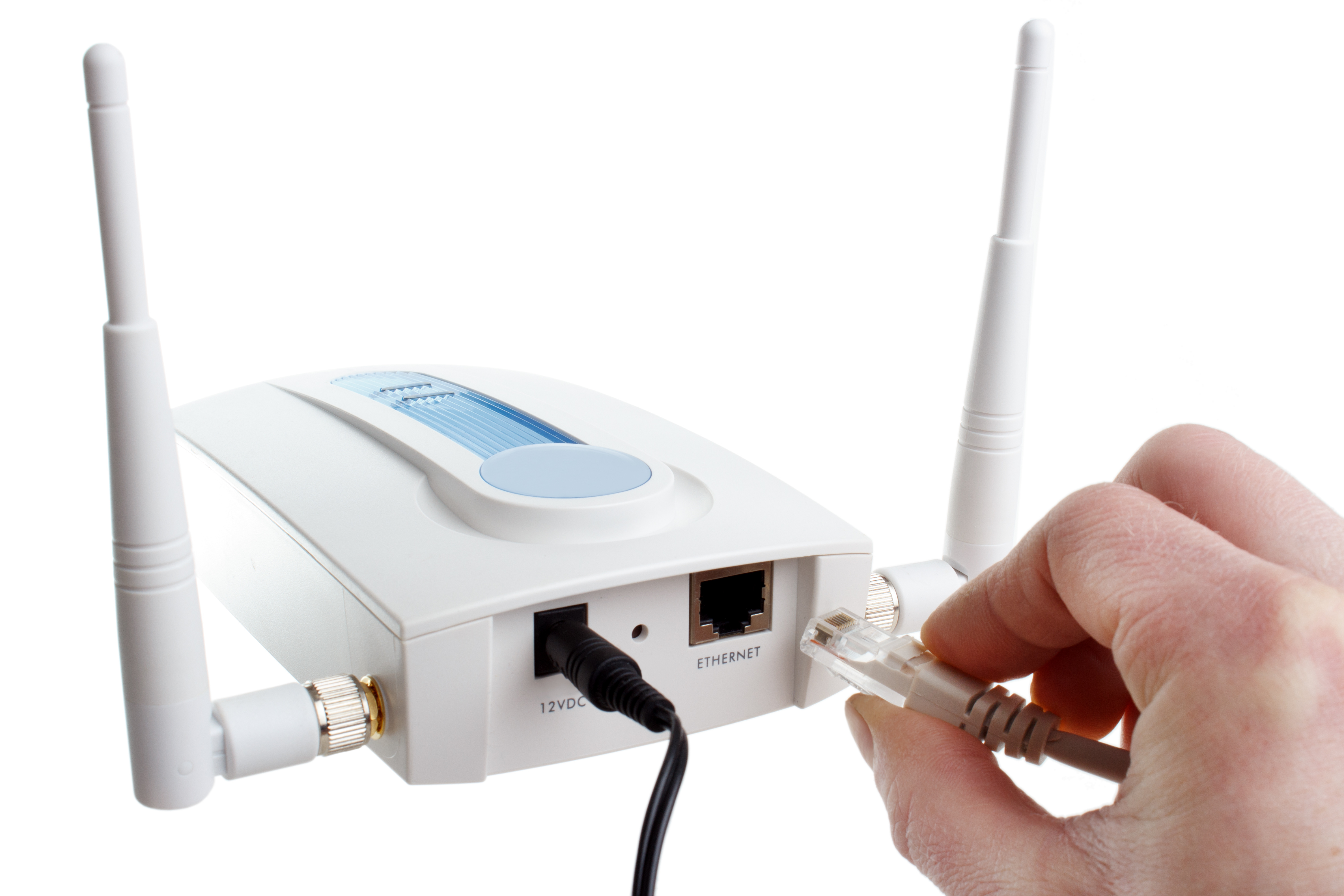
Let’s walk through an example to see how you can implement hitless failover with the Dual-Input Redundant PoE PD with Smooth Transition Reference Design and a WAP like the one shown in Figure 1 with dual PoE inputs and a single AC/DC wall adapter input.
 Figure 1 WAP with Dual PoE and Single
AC/DC Adapter Inputs
Figure 1 WAP with Dual PoE and Single
AC/DC Adapter InputsIn this example, the goal is to avoid data loss at all costs. Implementing three power supplies (two DC/DC PoE supplies and one AC/DC wall adapter supply) decreases the probability of power (and thus data) loss. In the event that the primary power source is unavailable due to harsh conditions, accidental trips or cable damage, one of the secondary power sources quickly transitions to become the main power source without dropping the output voltage at the load.
To implement hitless failover, you will need to choose a PoE PD device that has the automatic maintain power signature (MPS) and inrush delay features integrated – devices like TI’s TPS2372 or TPS2373 Institute of Electrical and Electronics Engineers (IEEE) 802.3bt PoE PDs, which can power loads up to 71W. The auto MPS feature is an electrical signature presented by the PD to assure the PSE that it is still present after applying the operating voltage. This automatically generated signature allows the PD to remain connected to the power sourcing equipment (PSE) and in active standby mode in the event that the main power supply goes down.
Now, let’s take a look at the hitless failover power transition as shown on the oscilloscope. In the reference design the adapter has power-supply priority over PoE1 and PoE2. Now, imagine that the adapter supply fails.
As shown in Figure 2, the output voltage of the AC/DC adapter (green) suddenly drops to zero while the output voltage of the secondary power source PoE2 (blue) transitions to being the main power source. During this transition, the input voltage to the WAP (yellow) remains constant at 5V. This enables the load to remain powered and for data to transmit continuously, even during the transition between power supplies.
 Figure 2 Adapter and PoE Power
Transition with Hitless Failover
Figure 2 Adapter and PoE Power
Transition with Hitless FailoverHitless failover power transition has become increasingly important due to the need for data-sensitive end equipment to avoid the loss of data transmission. If you are interested in enabling hitless failover in your PoE PD design, consider using a device with auto MPS and in-rush delay integrated such as TI’s TPS2372 or TPS2373 and the reference design I described here.